 Connect with Google
 Connect with Facebook
Tensile strength: Additive manufacturing vs Injection molding
Posted By Phil Lambert on May 14, 2014 | 0 comments
This is the final installment of the “Material Considerations for Additive Manufacturing of Polymers” series investigating the tensile performance of polymers processed with Additive Manufacturing. To quickly recap, Part 1 of this series described two AM manufacturing technologies, Fused Deposition Modeling (FDM) and Selective Laser Sintering (SLS), and introduced two materials that the FDM and SLS systems can process. Part 2 examined the tensile properties of materials processed by FDM and SLS. The third and final part to this series aims to better frame the tensile strength data of the AM fabricated parts by comparing them to a more traditional manufacturing method: injection molding.
Tensile Strength of Injection-Molded Parts vs. AM Parts
To understand the comparative performance of AM parts to traditional injection molded specimens, the researchers at DMRC generated standard stress-strain curves. A stress-strain curve show the relationship between the deformation (strain) of a material exhibited as a result of tensile loading (stress). The first chart shows the stress-strain relationship of Ultem 9085 test specimens printed with FDM versus the same test specimen manufactured with injection molding. The injection molded data is represented by the blue line, and the solid red line represents FDM data from a sample oriented in the X-direction during printing.
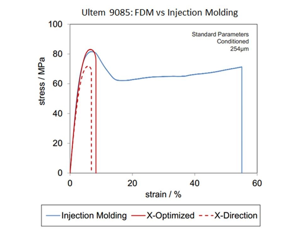
The FDM part printed in the X-direction performed equivalently to the injection molded part in stress, but fractured at a much lower strain. The data above neglects to include the Z-direction performance. The chart also alludes to the idea that tensile performance can be improved by changing some FDM process parameters, but that is information better saved for a separate post.
The final chart shown below compares the tensile properties of PA12 fabricated via SLS versus parts manufactured with injection molding. The data representing the sample printed in the X-direction is shown in red, the sample printed in the Z-direction is shown in green, and the injection molded sample is in blue.
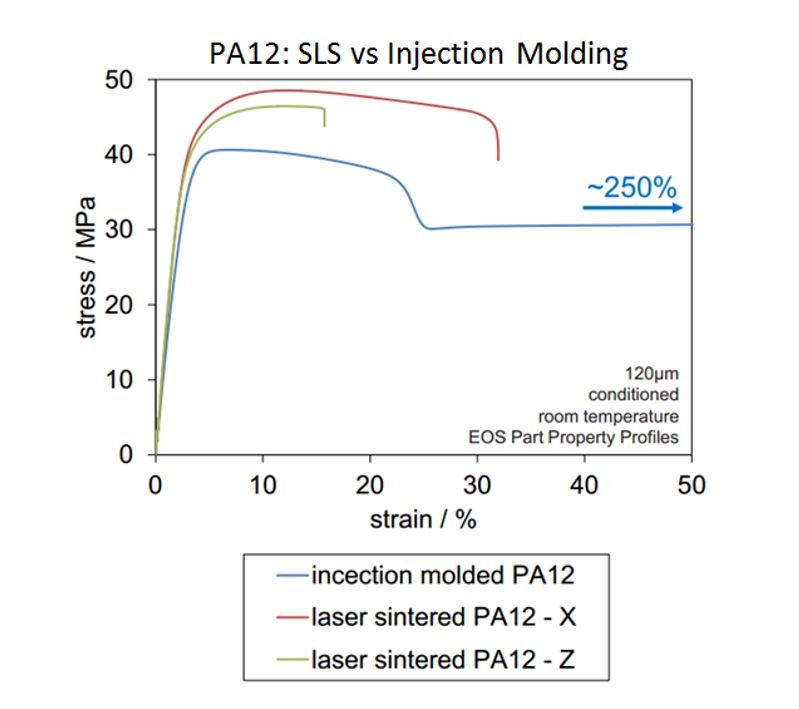
Both the SLS print orientations demonstrated higher stress than the injection molded part, but, like the FDM part, ruptured at far lower strains.
The stress-strain curves for Ultem 9085 and PA12 show that the AM manufactured parts can exhibit similar strength to the injection molded parts, but exhibit much lower strain break. The lower strain can most likely be attributed to the internal structure of the parts. Compared to AM processes, injection molding typically has lower porosity and greater homogeneity, leaving fewer imperfections in the structure of the material to encourage crack propagation.
Design Considerations!
After reviewing the data generated by the researchers at DMRC and presented in “Material Considerations for Additive Manufacturing of Polymers” series, there are several trends that stand out. These trends can be translated into four considerations to keep in mind when designing a part for additive manufacturing of polymers:
- The print orientation of a part is critical to tensile strength.
- FDM test specimens have much higher tensile strength when printed in the X or Y direction than the Z-direction.
- SLS printed parts demonstrate far greater isotropy than the FDM printed parts.
- FDM and SLS parts can exhibit similar tensile strength to injection molded parts, but fracture at much lower strains.
This means that choosing a system to print your part is very dependent on your application. This also means that a part designed for one system may not perform (or even print) equivalently from another. This information does not suggest that one process is the best for making high tensile strength parts, as it compares only two representative materials. New materials are always being adapted to be used in Additive Manufacturing, and process parameters for the machines are constantly being improved. As a result, the design space is constantly changing.
I hope these design considerations make the complicated problem of designing for Additive Manufacturing of polymer a little bit easier. More “Design for AM” posts to come!
**********************************************

Phil is a 3D Printing (3DP) and Design for Additive Manufacturing (DfAM) expert with a background in mechanical engineering. Hailing from the DREAMS Lab at Virginia Tech, Phil has over three years of additive manufacturing experience in designing and building 3D printers as well as using them to make what he considers to be some really, really cool stuff. He plans to bring a mechanical engineer’s perspective to the Sculpteo blog by providing insight into the unique constraints and abilities of 3D Printing with an eye towards mechanical, material, and process considerations.
*********************************************
Check out Stratasys FDM thermoplastics here.
Visit the EOS materials database to learn about other SLS powders.
Research Credit: Matthias Fischer and Stefan Josupeit from DMRC (Direct Manufacturing Research Center)
“Material Properties of Additive Manufactured Polymer Parts”, Inside 3D Printing Conference and Expo, Berlin, March 11, 2014”