 Connect with Google
 Connect with Facebook
The twisty puzzle of 3D printing
Posted By Felix Nadin on Apr 6, 2016 | 0 comments
Everyone knows the Rubik’s cube. This puzzle originally designed in 1974 by Ernö Rubik has become a symbol of the 80’s and is still today the most sold toy around the world. Between the 80’s and 2000, many twisty puzzles using the same principle as the original cube have been invented and a community of fans was born.
The number of new puzzles per year increased over the years but a real revolution happened between 2008 and 2010 for the universe of twisty puzzles: 3D-printing. With this new technology, people could design puzzles at home and produce them easily without anything else than a CAD software and their imagination.
But every twisty puzzle designer knows that the tricky part of designing a puzzle is not to think of the puzzle but to make it twist. Even if you have a very good idea about the different parts the puzzle will contain, the number of mechanical pieces can be very high and cause misalignment, high frictions, and instability in the puzzle. The prototype could be too tight and impossible to turn or too squishy and explode as soon as you try to solve it (the right term is to pop). Beyond puzzles, we’ll try to have a look here into micro-mechanical systems and how to design them.
Puzzle design : best practices
Our study case will be the original Rubik’s cube. If you’ve already lost patience and dismantle the cube to build it again or if you’re simply curious, you may know the mechanism of this puzzle.
Instead of being cut straight into 27 smaller cubes, the Rubik’s cube is cut with a special profile to make sure parts hold together.
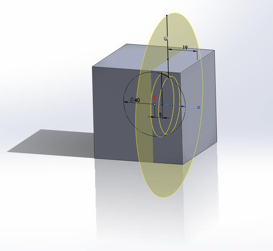
This yellow surface is one of the six surfaces (the mirror version of it in the three dimensions) that divide the cube into cubies
The parts coming from this division are composed of three types of pieces :
- Centers have one visible faces. They are linked together to a central core invisible from the outside. They will turn around it.
- Edges have two visible faces. They are held between two centers.
- Corners have three visible faces and are held between three edges.
There are six centers, twelve edges, and eight corners.
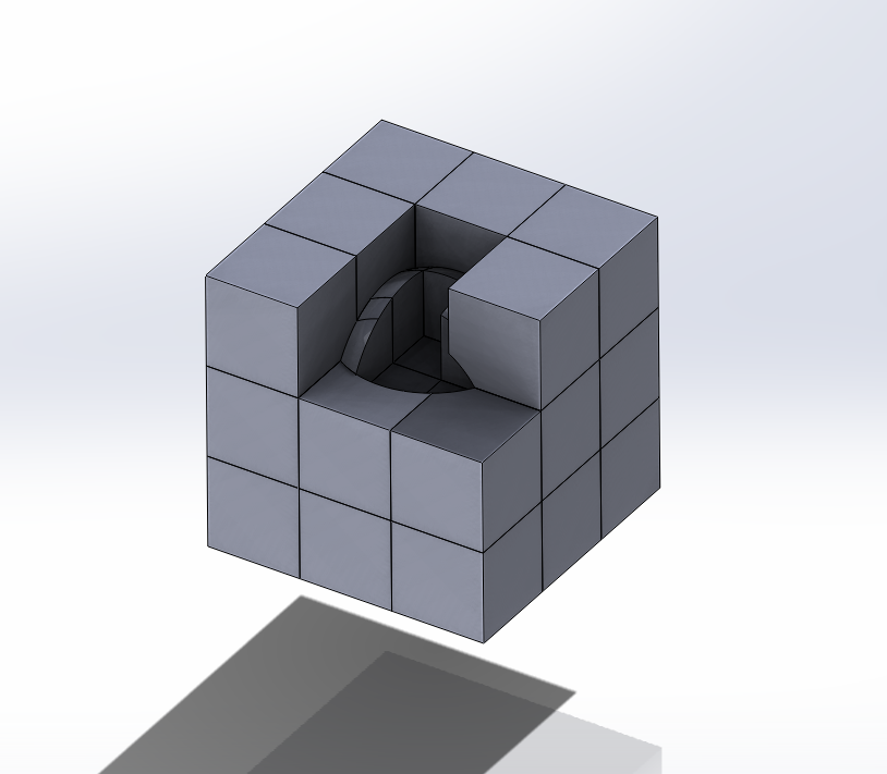
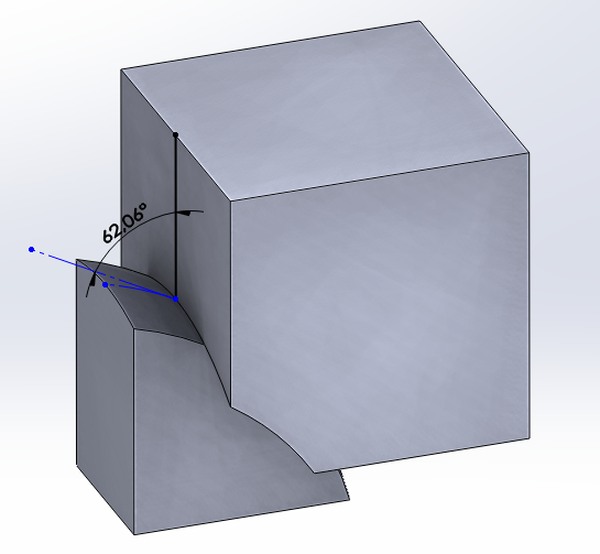
What you see here is the simplest design we can imagine for this puzzle but from a mechanical point of view, it has to be slightly modified. Indeed, some surfaces are forming an angle that is under 90° which can generate jamming between parts. To avoid this, the sketch has to be changed as following :
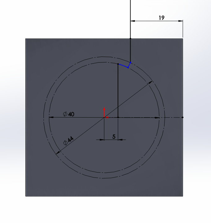
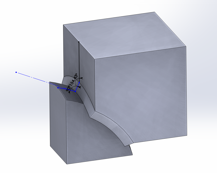
This sketch contains only angles over 90°.
Before jumping to the next step, check that all parts respect the technical requirement for 3D-printing like wall thickness, hollowing rules, etc.
Set the mechanical clearance
This is probably the most difficult step in your design because a tiny change in clearances can totally change your mechanism behavior. Even if any prediction is hard here are some best practices for clearance well known by puzzle designer that can make you save time and money.
There is two kind of clearance in a mechanism :
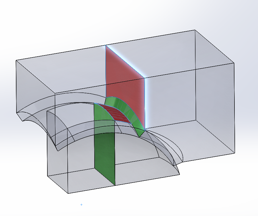
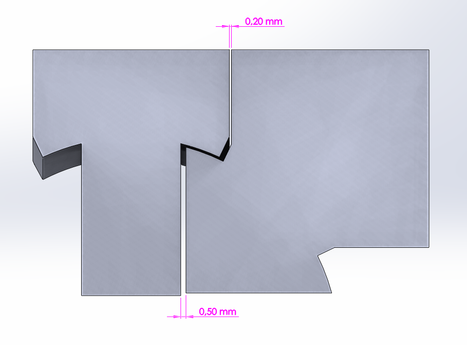
- Small clearance between surfaces that pull or slide together : 0,2 mm / 0,008 in (red surfaces)
- Large clearance between parts that hover and need no contact while working : 0,5 mm / 0,020 in (green surfaces)
A third kind of clearance is usually pointed out for parts that jam (axes for example) but same clearance as the small one can be used.
With this clearance, you’ll get a smooth turning puzzle without any polishing required. If you’re planning to use the mechanism very often, if you design a cube for speed solving that you’ll use for all your competition, for instance, a different clearance should be used to anticipate the wear of plastic. Small clearance will be deleted (0mm/in) and large one reduced to 0,4mm / 0,016in. Clearance for jamming parts won’t be changed.
If the puzzle seems hard to twist at the beginning, it’ll be smoother and smoother.
Add well-chosen fillet
The final step of your design is to add fillets to the edges of each of the parts you’ve created. This fillet will avoid parts from blocking the puzzle if misaligned. A 2-3 mm / 0,08-0,12 in fillet is a good value (see orange fillets on the picture).
You can also add a 1mm / 0,04in fillet on the visible faces to make your puzzle look good (blue fillets on the picture).
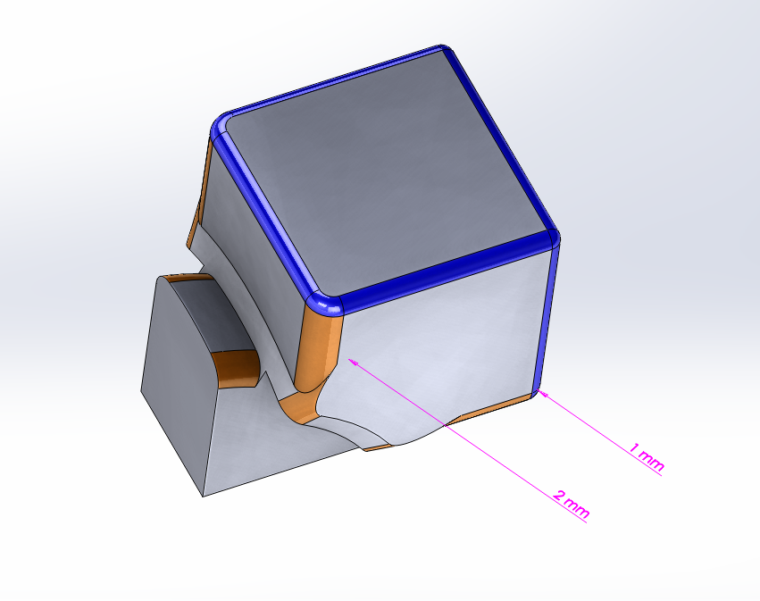
Orange fillet makes the puzzle turn better. The blue one only has an aesthetic use.
Of course, don’t forget to hollow your parts through your CAD software or with our hollowing tool to get a lighter puzzle and save money.