 Connect with Google
 Connect with Facebook
SLS and Carbon’s CLIP: Our prized in-house technologies
Posted By Melchior de Wargny on Sep 14, 2016 | 0 comments
Have you ever wondered what Carbon’s CLIP technology is all about? Did you ask yourself how it compares to one of the most used technologies in professional 3D printing: Selective Laser Sintering (SLS)? Well today, we will be comparing the two technologies to discover the benefits of using both technology for your projects!
Two weeks ago, we talked about three classic 3D technologies, Fused Deposition Modeling (FDM), Stereolithography (SLA), and Selective Laser Sintering (SLS), and how they compare to one one another. There was much to say as the technologies are well known, but the same thing cannot be said for the CLIP technology. CLIP was introduced in 2014, since then we have been discovering the best application opportunities. Carbon is constantly iterating and improving on their technology; as part of this effort, they continue to refine their hardware, software and materials. In the end, choosing between SLS and CLIP to print out a prototype or production part, is dependent on what is expected out of the part.
The technologies
Selective Laser Sintering (SLS)
EOS Formiga P110
As discussed two weeks ago, the concept behind Selective Laser Sintering is quite simple, but the execution is usually reserved to professional companies and online 3D printing services as ours, since SLS printers are usually large (as large as a double door American fridge) and costly. To summarize the idea behind it, a powder from a container is swept upon the build stage by a recoater, a laser then selectively scans the thin layer of powder, sintering together powder particles in the shape of the cross-section of the first layer of the design, as we can see in the image above. The build platform is then lowered one layer depth and the recoater applies a new coat of powder. Just like the first layer, the second cross-section of the 3D design is scanned and sintered while being adjoined to the first layer making a solid part. The process is iterated until the object is completed. The tray containing the completed object is then removed, and the objects are de-powered. No further process is needed, apart if you want to apply an addition finish (paint, polish, dye, smoothing beautifier…).
Continuous Liquid Interface Production (CLIP)
Carbon M1
CLIP, which stands for Continuous Liquid Interface Production, eliminates shortcomings of other 3D printing technology by emphasizing a tunable photochemical process over a traditional mechanical approach.
Carbon’s technology works through two phases. The first one, CLIP, consists of shaping the part by projecting a light through an oxygen-permeable window into a reservoir of UV-curable resin. As the UV images are projected in a sequence, the part solidifies and the build platform rises. This is similar to SLA with a slight difference: Carbon introduces oxygen into the liquid resin in order to control what is known as the “dead zone”. The “dead zone” is a thin, liquid interface of uncured resin between the window and the printing part where the light passes through.
The second phase consists of thermal curing by baking the parts in a forced circulation oven to set off the properties of the materials. Through this process, a secondary chemical reaction sets off and causes the materials to adapt and strengthen, ultimately achieving desired engineering-grade mechanical properties.
Resolution
When talking about resolution, we are referring to layer thicknesses of SLS and pixel size of CLIP. Both technologies offer a resolution within a certain range. However the typical resolution values for these two technologies are different as each individual printers have their own specifications.
Layer thicknesses on SLS 3D printers vary usually between 50µm and 150µm range, with the horizontal resolution depending strongly on the design itself, but usually on the 200µm to 300µm range.
On our Carbon M1 printer, the pixel size is 75µm. The CLIP technology produces monolithic (solid), layerless parts. Because parts are layerless, it has significance on the microscopic level, where there are no pores that might contribute to the weakness of a part.
At Sculpteo, the default slice thickness for SLS polyamides is around 100 to 150 micrometers and 100 micrometers for CLIP resins, but it is possible to print thinner slices for a smoother appearance. In fact, we offer the option to print out at 60 micrometers using our white plastic to have a smoother surface.
Mechanical properties
White Polyamide (PA12) tensile test
Our white plastic and black plastic objects are made using SLS, layer by layer, which means that their properties are not the same in every directions, they are anisotropic materials. Indeed, cohesion between two layers is weaker than between the grains of powder of a same layer. When pulled perpendicularly, the material yields more easily than in the direction of the layers.
For our white plastic, we get in average:
- A Young’s modulus of 1,78GP for horizontal prints and 1,52GPa for vertical print.
- A strain at break of 21% along the layers and of only 8% perpendicularly.
- A tensile strength of 48MPa along the layers and of 35MPa perpendicularly to the layers.
Black plastic, being more flexible than white plastic, has in average:
- A Young’s modulus of 1,87GPa for horizontal prints and 1,84GPa for vertical prints.
- A strain at break of 22% along the layers and of only 16% perpendicularly.
- A tensile strength of 45MPa along the layers and of 48MPa perpendicularly to the layers.
Rigid Polyurethane tensile test
Unlike the conventional 3D printed materials, such as the polyamide used in SLS, CLIP parts behave consistently in all directions, they are isotropic. Strength and mechanical properties do not depend on the direction in which they are printed.
Looking at the materials available at Sculpteo:
- For Cyanate Ester, we have:
- A Young’s modulus of 4.5GPa.
- A strain at break of 4%.
- A tensile strength of 110MPa.
- Heat deflection 219 degrees C
- For Rigid Polyurethane 70, we have:
- A Young’s modulus of 2.2GPa.
- A strain at break of 100%.
- A tensile strength of 55MPa.
- Heat deflection 70 degrees C
- For Prototyping Acrylate, we have:
- A Young’s modulus of 0.95GPa.
- A strain at break of 28%.
- A tensile strength of 32MPa.
All-in-all, we can see that specific resin’s have specific properties adapted to specific situations. Carbon’s Cyanate Ester for example has excellent thermal stability and chemical resistance perfect for jobs where high temperature is a factor. Their Rigid Polyurethane materials (similar to nylon or ABS), on the other hand is compatible with most uses.
Surface
A number of different materials can be used on SLS printers, however, the object will remain in a single material. Regardless of the material chosen, the surface of an object created by sintering powder is always slightly rough, similar to a sanded surface. Indeed, as the powder particles are not completely melted but just sintered, some of the microscopic granularity of the powder remains on the object’s surface. Nonetheless, the microscopic granularity is not something that can be easily seen with the naked eye, but can be felt on the skin.
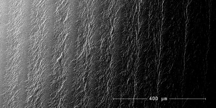
Traditional 3D printed parts with a layer-by-layer approach (SLA)
On the other hand, parts printed with CLIP are much more like injection-molded parts, the result is a solid homogeneous part. CLIP produces consistent and predictable mechanical properties, creating parts that are solid on the inside.
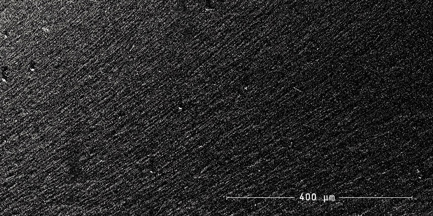
Part produced using Carbon’s CLIP technology
Support
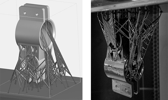
Due to the nature of the CLIP process, support structures are necessary for complex and intricate object designs that have attributes like overhangs or do not have a clear standing position on the build platform of the M1. Supports are removable structures placed along part geometries in the CAD file that hold up overhangs and help anchor features of the model to the platform. They can be bars with tapered tips, trusses, or lattices, all of which aim to improve the object’s final properties and printability. Features that often need supports include overhangs small angles and floating structures.
The supports are built from the same material that the part is printed with as using a secondary support material is not an option, therefore, supports are physically bonded to the final printed part and have to be latter detached by hand.
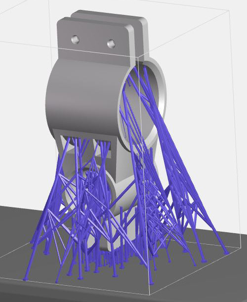
Supports are often required when using the CLIP technology
SLS, does not require support structures since the powder acts as a self supporting material. This allows intricate and complex geometries to be constructed, there is an almost complete design freedom.
Post processing
While SLS has several post processing options, only one is available as of today for the printed CLIP parts at Sculpteo.
SLS finishing options include:
- Raw: sandblasted but unpolished, surface remains somewhat rough, most economical.
- Polished: polished through mechanical polishing, smoother to touch, layers still somewhat visible on rounded objects.
- Smoothing Beautifier: smoothed through a physico-chemical process, the objects finished with our exclusive Smoothing Beautifier process have a glossy surface.
- Dyeing: dyeing colors the object and reaches all surfaces of the part, including the most inaccessible recesses, resulting in a very uniform finish.
- Painting: gives a color to the material in any of the available paints with specific RAL.
- Varnishing: give the object a shiny appearance and, depending on the varnish, protects it from UV.
Two finishing options are available through Sculpteo for CLIP parts:
- Raw: Supports are removed from the model. Support scars/bumps may still be visible.
- Polished: Supports and support scars/bumps are removed.
It is important to note that through the CLIP process, objects can be printed in custom colors using Prototyping Resin, so the necessity to dye or paint is less important than the polyamides used in SLS which come out either white, grey or black.
Food/Chemical compatibility
Our white plastic, printed using SLS, is both food compatible and biocompatible. Indeed, as the laser sintering process is in compliance with the EU Plastics Directive, the use of plastic printed objects with all types of food (excluding alcoholic items) is permissible and does no harm.
Concerning chemical compatibility, SLS polyamide objects can withstand some solvents like Acetone, Petrol, and other chemicals. A full list exposing chemical resistance of our nylon is available on our plastic material page.
As for the CLIP technology, tests are in progress to determine food and chemical compatibility of CLIP resins.
Costs
The cost of a SLS machine is pretty steep, which is why it is mainly used for industrial applications. The cost of the material, Nylon, is on the other hand quite inexpensive as it is a pretty common material outside the 3D printing circle. Furthermore, as Sculpteo has made the technology available to everyone, and since SLS printers can output large quantities of objects in a single run, SLS prints are usually on the cheaper side.
CLIP resins cost between $99-$399 for 800mL . The materials’ mechanical properties make them more interesting for industrial applications where high impact strength or high temperatures resistance are needed. Prototyping Resin (PR) is the least expensive and is great for part design iteration and quick prototyping needs.
Summary
To try to generalize trends, we set out to define a table with general terms and components to define each technology to enable everyone to choose between them according to their needs and wants.
| SLS | CLIP | |
| Material | Polyamide (Nylon), Polystyrenes, Thermoplastic Polyurethane (TPU),Metal | Photosensitive ResinsRPU- Rigid PolyurethaneCE- Cyanate EsterPR- Prototyping Resin |
| Achievable quality | High | High |
| Layer thickness | 0.05 to 0.01 mm | 0.001 to 0.01 mm (refers to slicing of part in the M1 software) |
| Minimum wall thickness | 1 mm | 0.5 mm |
| Surface texture | Slightly rough but can be polished | Smooth, often shiny |
| Colors (without post-process) | Opaque White, Gray and Black | RPU- Rigid Polyurethane (Black)CE- Cyanate Ester (Amber Translucent)PR- Prototyping (CMYK+WG) Resin |
| Support (complex designs) | Not required | Often Required (Geometry dependent) |
| Mechanically | Strong and flexible | RPU (tough, abrasion resistant, stiff)CE (high temp resistant, strong, stiff) |
| Mechanical failure | Gradual deformation until fracture | Almost no deformation until sudden fracture |
| Abrasion resistance | Good | Good (much better than SLS) |
| Post-process | Polishing, Smoothing Beautifier, Varnishing, Dyeing, Painting | Polishing |
| Food compatibility | Yes | Testing in progress |
| Chemicals compatibility | Highly resistant (Nylon) | Testing in progress |
| Cost | Printers very expensive,Material inexpensive | Printer $40k/year subscription,Resins $99-$399 mL |
For more information about the technologies or materials, you can go check out our blog onSLA vs.SLS vs. FDM which gives a brief summary on each technology, SLS vs. SLA which goes further into details of each technology, our comparison page on FDM vs. SLS which shows examples of both technology and compares them, or our glossary pages on SLS, FDM, SLA, Nylon, ABS, and much more.