POLYMER POWDERS
PHOTOPOLYMER RESINS
POLYMER FILAMENTS
Login
If you have any trouble logging in to your account, contact us.
Sign Up
To start 3D printing or Laser Cutting, you'll need to create an account here. Once done, you'll be able to upload your files and get live quotes of yours parts
Already have an account? Log In
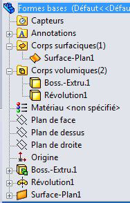
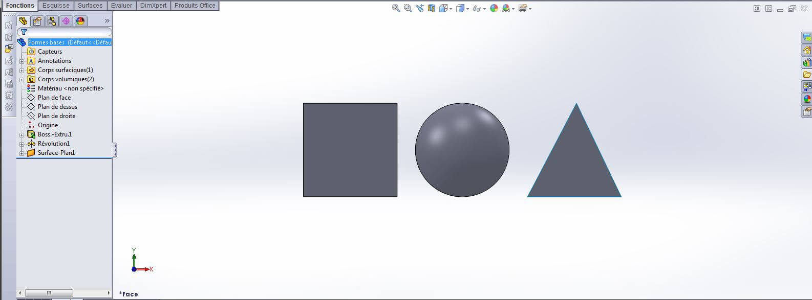
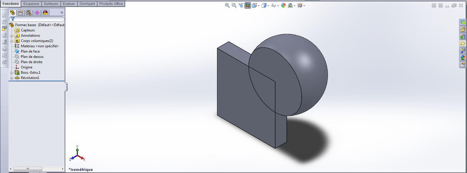
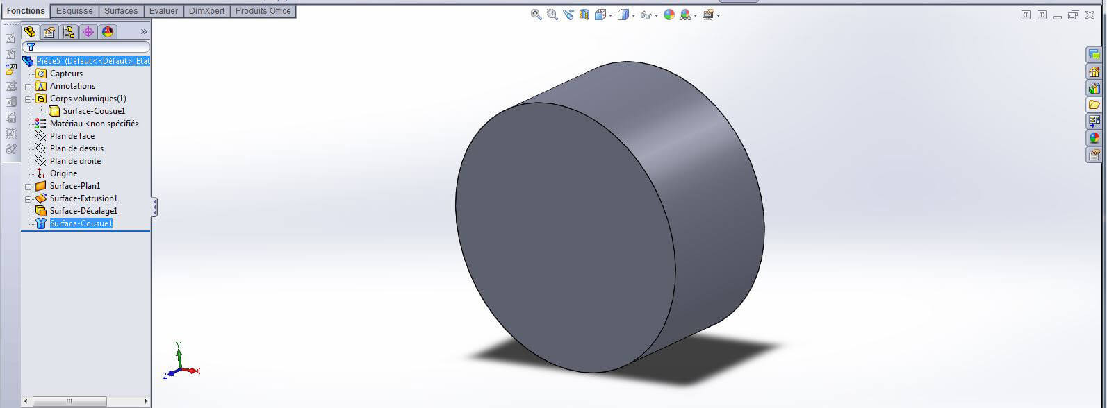
SolidWorks offers two principle types of modeling: Solid and Surface. Each object within the program is called a body. It is possible within SolidWorks to create a body through one of the two types of modeling, or by merging two existing bodies together.
You can see the total number of solid and surface bodies at the top of the scroll down menu on the left side of the interface.
Surface modeling allows for particular advantages, such as when creating car bodies, waves, or other specific forms. However, for a 3D print, it’s better to export a file that only has solid bodies. This because surface bodies do not have a recorded virtual weight and thus cannot be translated into a physical form. It is necessary that your 3D model has a minimum weight corresponding with the limits of the material to be used in the printer so that the printer can correctly apply the information.
It is possible to work with surface bodies only which we will mention in a later chapter. For now, let’s begin working solely with solid bodies
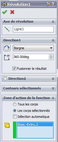
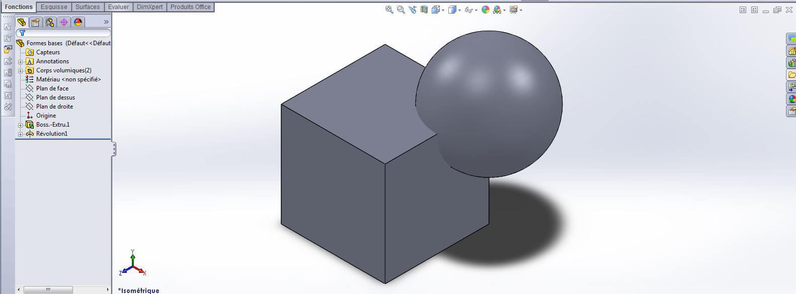
To create a file with a single body in a solid modeling mode, check the “Merge Result” option in the scroll down menu that appears with the function, then check “Selected Bodies”.
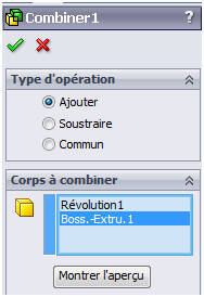
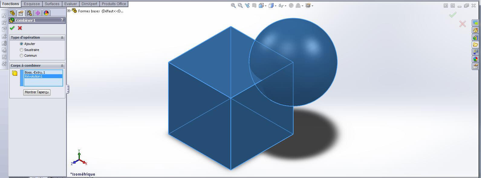
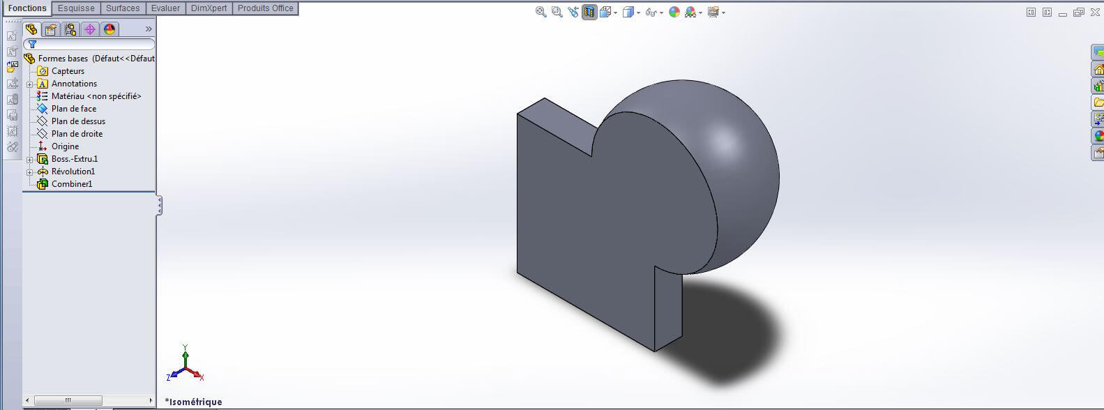
If you are unable to check this option when running the function or if you prefer not to immediately merge the bodies, it is always possible to merge multiple bodies with SolidWorks’ boolean tool. You can find this tool under Insertion>Functions>Combine and use the “Add” option until you arrive at a single solid body.
Every function applied through SolidWorks generates a volume that adheres to 3D printing conditions, assuming they align with the anticipated material of the print.
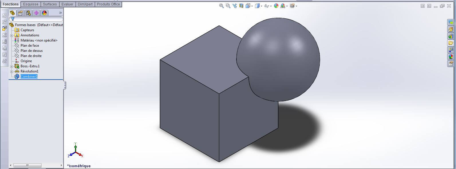
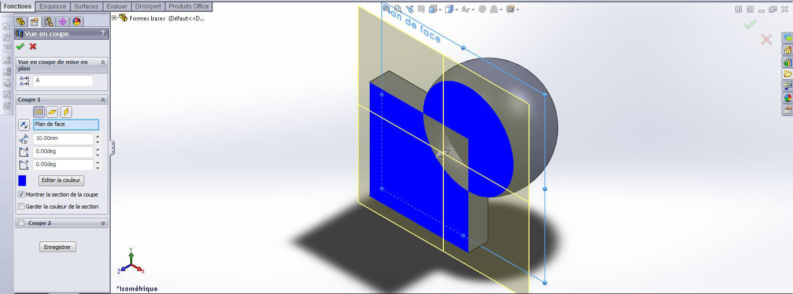
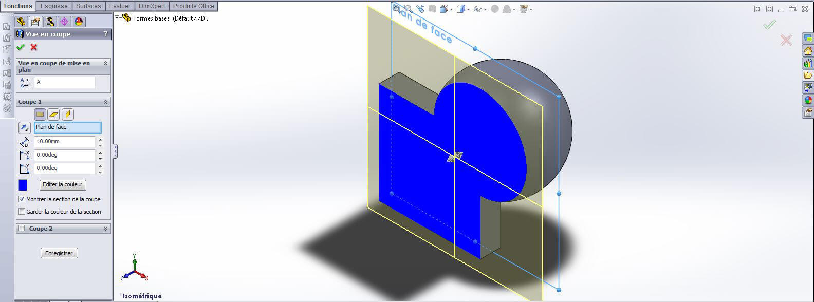
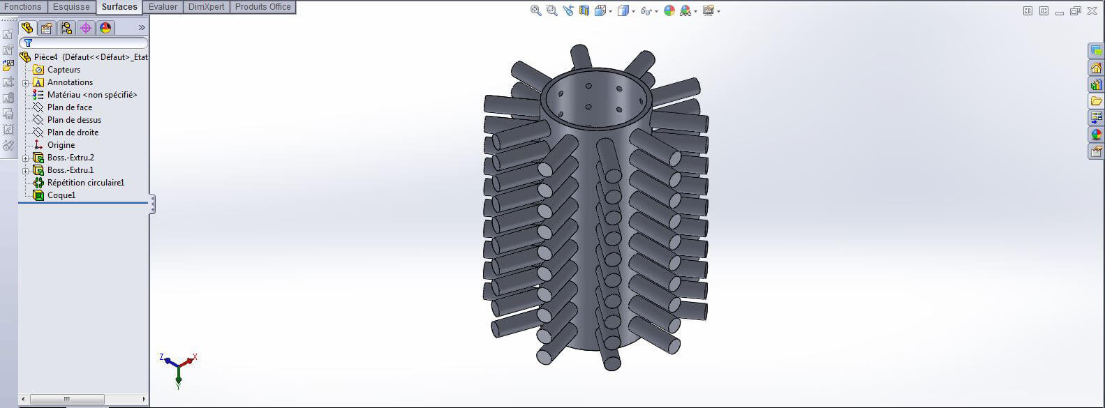
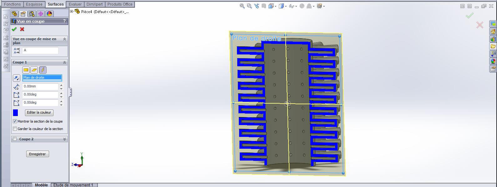
You can verify whether or not your model is fully merged when looking at a cut view. Merged bodies will produce a solid color blue, whereas intersecting bodies will not.
Note: in the two photos below, the bodies are not merged and the cut section of the objects produces a gap in the blue coloring.
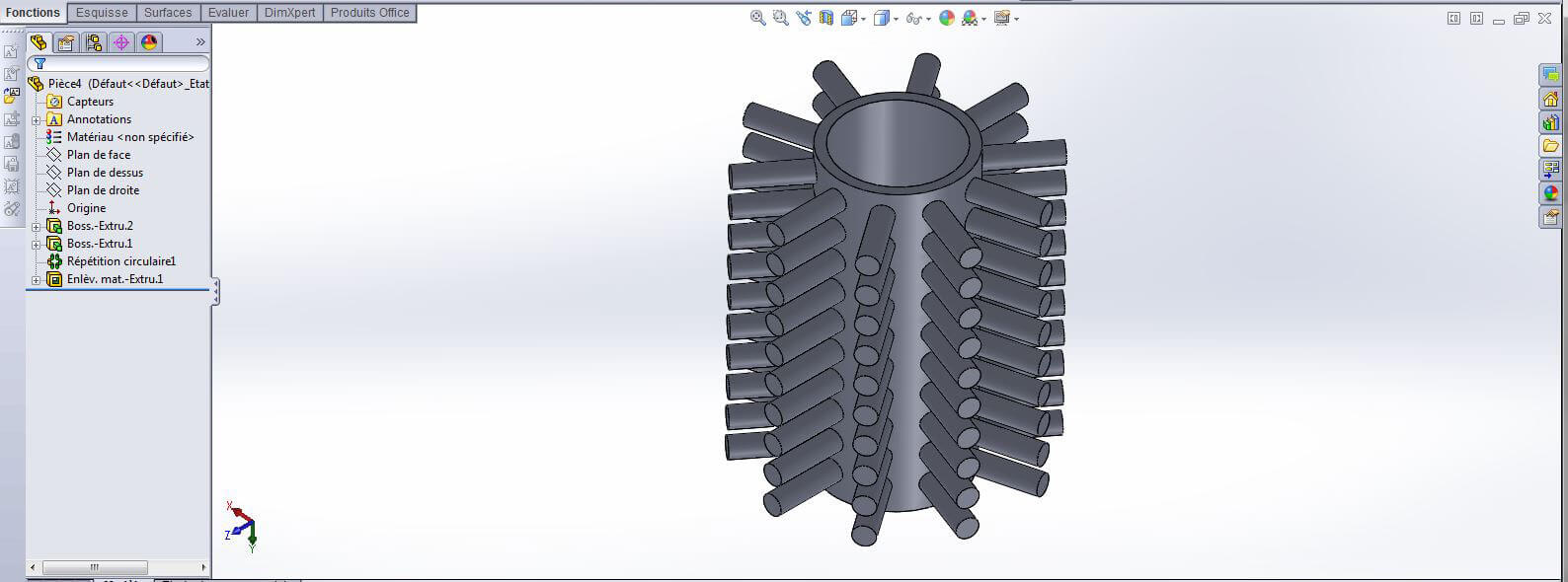
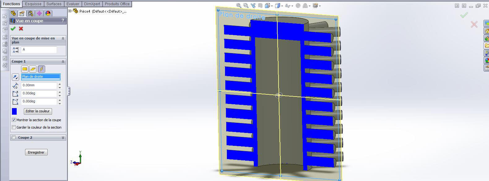
After using the “Combine” tool, a cut section of the two bodies produces a solid color blue, meaning the bodies were successfully merged.
If your design can be created without surface functions, we highly recommend using only solid functions for your 3D print. The majority of functions (extruded boss/base, revolved boss/base, swept boss/base, loft boss/base) are the same in both modes. However, it is possible to use surface functions if necessary. In the following section, you will learn how to render a printable model using surface tools.
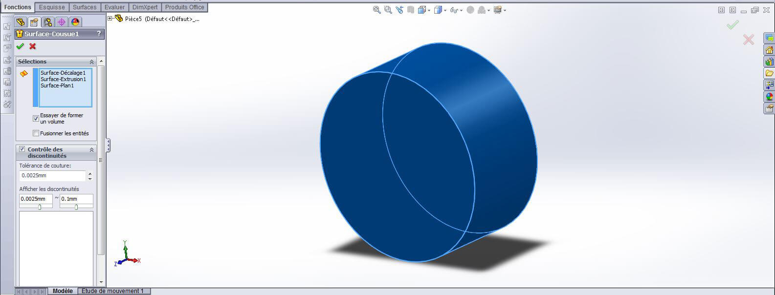
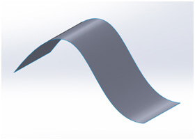
To create a printable surface model, it must be converted into a solid before exporting. So it’s important to keep in mind that the surface bodies you create will eventually be converted into solid bodies.
To accomplish this, your surface bodies must be closed with continuous, common, and finite borders. In other words, it must be watertight. This allows for an easy conversion of the surface ‘skin’ into a solid body.
Another option is to use the “Thicken” tool, which allows you to determine the thickness of your surface and that of the physical print. If you decide to use this option, keep in mind the minimum requirements for the material you plan on printing with.
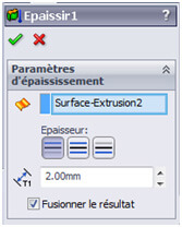
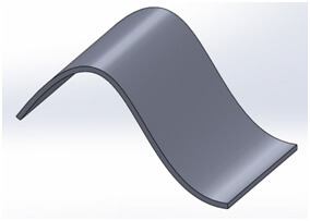
Also, note that the “Thicken” tool can be found in the “Boss/base” menu, which is usually associated with solid functions. Performing this task will convert your object into a solid body.
Creating a hollow model is important for 3D printing as it limits the amount of material used to create the object. A hollow object will greatly reduce the cost of the production, and some materials require specific sizes to ensure a successful print.
There are a couple options for hollowing a model.
You can upload your file to our website where the object can be automatically hollowed through a Hollowing function. The function will also place a small hole in the object to allow the excess printing material to drain during the printing process.
If you would like hollow your object directly in SolidWorks, the “Shell” function can accomplish this. Though keep in mind that you will have to choose the surface on which you will place you draining hole and the thickness of the walls.
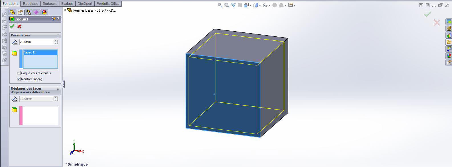
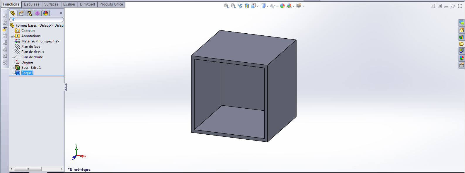
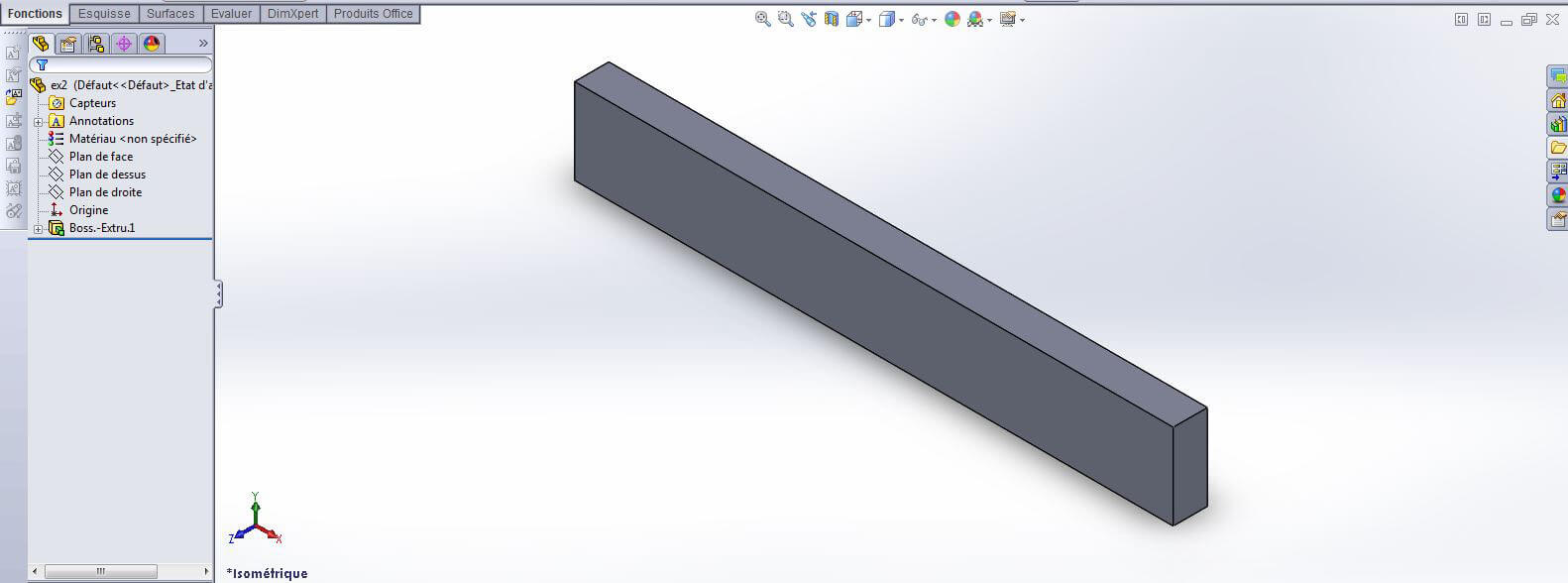
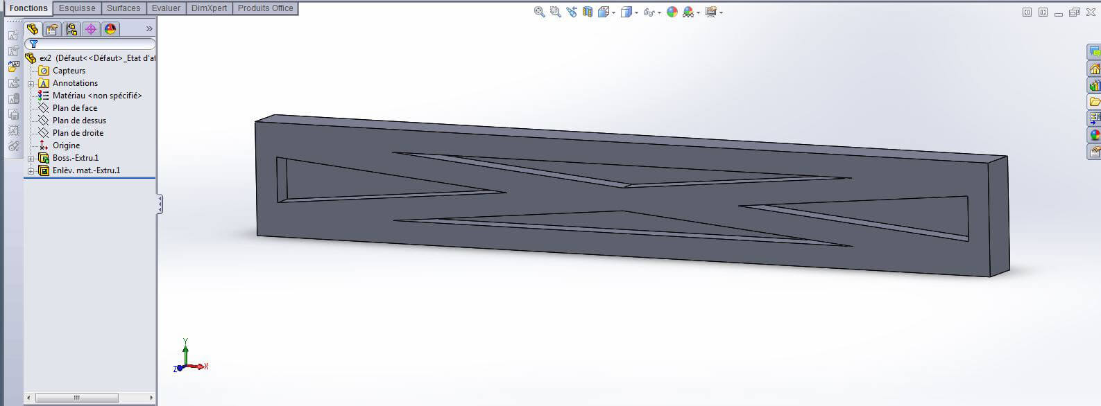
Not all pieces need to be hollowed. However, sometimes more fragile parts ought not to be hollowed. And in other cases, basic engineering designs can reduce the total about of material used all the while maintaining structural properties. Note the examples below where material can be reduced, and where it ought not to be:
If you select the “Hollow” function without selecting a face to allow the object to empty, be sure to allow a hole in order to allow excess material to drain. Without a hole to allow the excess material to drain, the object will be interpreted as a solid object and will be printed and priced as such! For more information about how big the holes should be, please check our Materials page.
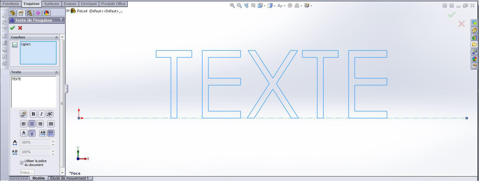
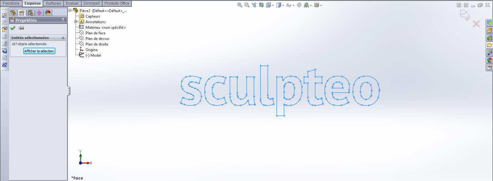
It is possible to add relief text or motifs to your objects using online Sculpteo tools, but you can accomplish the same thing using SolidWorks. If you would like to integrate text on your model, you can either:
To use the text tool in SolidWorks, you must first select the orientation of the text and after that, you can add your text and modify the typography as you see fit. You can then use the outline like any other sketch in the program and can apply functions to it.
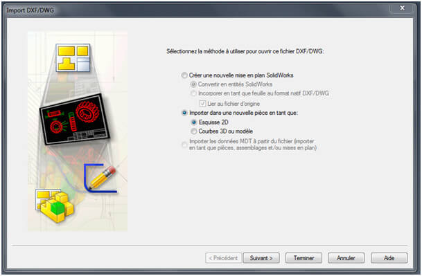
If you would like to import a text, drawing, graphic, or any other sort of vectorized graphic into SolidWorks, make sure it is a .dwg or .dxf file. To import one of the files, click on “Open a file” > “Import into a new part as” > “2D Sketch”.
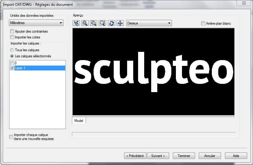
The following window will allow you get a preview of your file and to select the layers you plan on including.
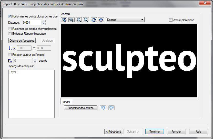
The following screen allows you to merge points of the drawing under a certain threshold. This is particularly helpful if a file is complex, where the automatic vectorization of the file may create performance and size issues in the resulting file.
It is also possible to change certain characteristics of the file on this screen (rotation, positioning, etc.) – though it is not particularly useful.
When you click “Finish”, your vector file will open in a standalone draw file. The easiest way to transfer it from there is by copy and pasting.
All that is left to be done is to adjust the size and positioning of the drawing with the traditional draw tools (size, placement, rotation, etc.).

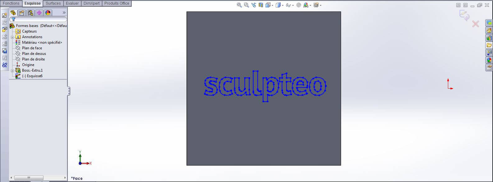
We advise leaving a point of reference on your piece so you will be able to quickly view your drawing with the “Go to” tool.
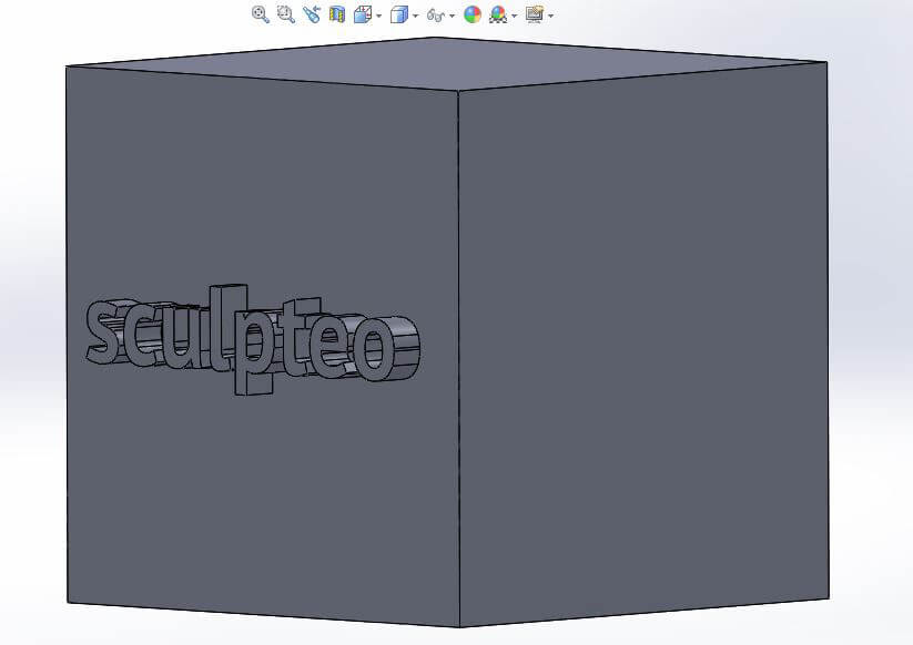
Any SolidWorks function can then be able to be applied to your trace.
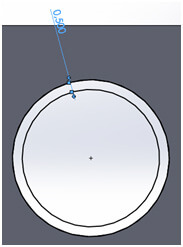
With 3D printing, you are able to print moving and articulated pieces in a single print. Your piece can be fully assembled and functional straight out of the printer – though there are certain rules that must be followed in order for it to come out correctly.
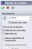
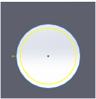
A plastic piece, for example, must have a clearance of 0.5 mm between surfaces. If not, the heat created during the printing process will fuse the objects together. If you’re interested in the particular restrictions of Sculpteo’s materials, visit our materials page. We will cover how to measure dimensions in the next chapter.
To measure objects to an exact distance, applying SolidWorks tools will be especially useful.


SolidWorks has a system to prepare the model for different materials which can also be integrated into 3D (photo view 360). However, the colors and materials generated are not exportable. It is impossible to directly export a SolidWorks file with textures.
There is an indirect way of exporting, which involves exporting the textures in a separate file, importing them into another program (such as Blender), assigning your textures in that program, and exporting it from there – though it is particularly laborious and there are many possible risks. We do not recommend it. If textures are an important part of your design we recommend designing them directly in another program.
 Connect with Google
 Connect with Facebook