Login
If you have any trouble logging in to your account, contact us.
Sign Up
To start 3D printing or Laser Cutting, you'll need to create an account here. Once done, you'll be able to upload your files and get live quotes of yours parts
Already have an account? Log In
Let’s now take a look at how to deal with incorrect meshes in Alias. It might happen that your mesh presents some mistakes that would make it unsuitable for 3d printing, these are normally due to common distractions or inaccuracy during the modeling phase.
At Sculpteo we have developed some great automatic mesh repairing algorithms that you can easily access online through our upload page. We can proudly say that these methods succeed in almost all cases in repairing common mesh problems, but as they are automated repairs, you might want to have better control on how your mesh topology should be modified following any repairs. Therefore when dealing with isolated and detectable errors, it is better to manually repair these errors yourself on your modeling software if it has the tools to do it, and Alias does have these tools.
The reason for manually troubleshooting errors is that no automated algorithm knows your mesh as accurately as you do.
Next, the tools Alias provides to solve the most common problems with invalid meshes will be discussed in the coming paragraphs. In this section, the common mistakes you can find in your mesh will be discussed and the repair process will be explained.
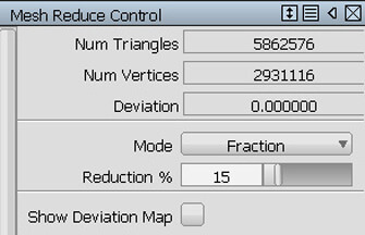
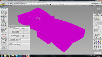
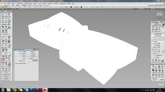
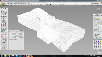
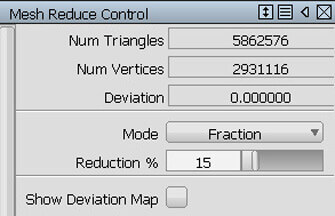
If your mesh’s ‘Number of Polygons’ is more than a million, it will be quite difficult for Sculpteo to handle it which also means it contains unnecessary details. Therefore, you need to reduce this number through the ‘Mesh Reduce’ feature.
This means that faces belonging to the same shell of your model might not have a coherent orientation, which means you then have to go back to the ‘Mesh Orientation’ paragraph and fix this issue using the ‘Reverse Mesh Orientation’ function.
Your mesh needs to be perfectly closed, or ‘airtight’, to be printable. The holes you might find are
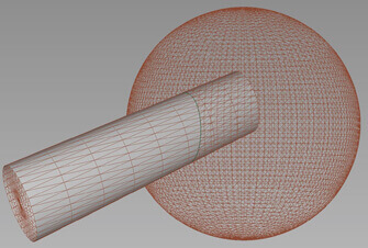
Every part that makes up your digital model needs to be made of just 1 shell, if this is not the case what you need to do is : separate these shells (With ‘Subset’), then intersect ( ) , cut ( ) and unify again (With ‘Mesh Merge’) to create just one shell.
If you see a boundary on your mesh that is not due to a hole or a non-manifold surface, it means that your model’s surfaces haven’t been stitched correctly. So simply go back to your surface model or stitch the mesh with the ‘Mesh Stitch’ feature.
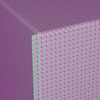
If you detect an edge on your mesh belonging to a single face on your model, and it’s not defining a hole, it means that this is the reason why your mesh is not manifold and printable. The best thing you can do is to go back to the modeling phase, or you can try to cut the unnecessary parts with ‘Mesh Subset’ and then stitch the edge with ‘Mesh Stitch’.
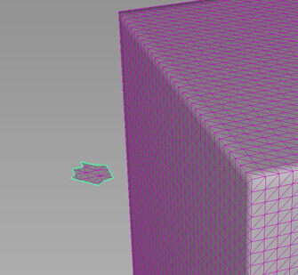
One boundary can also define one or a group of unwanted polygons that for some reason belong to your mesh. You can easily delete these polygons with the ‘Mesh Subset’ command.
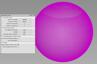
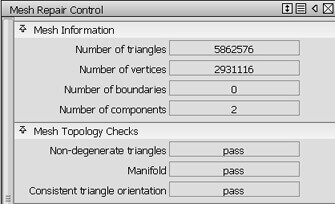
Going back to the mesh analysis –by Double clicking on Mesh>Mesh Repair—, seen in the previous chapter, check if some of these mistakes have been detected.
As already mentioned, Sculpteo’s upload limit for meshes is fixed at 1,000,000 polygons, because meshes with more polygons would be difficult to handle. If in the analysis phase you see that your mesh is bigger
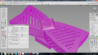
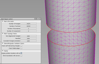
If your shells have not been properly stitched together during your modeling process, you might see some ‘Boundaries’ appearing on your ‘Mesh Repair’ window, which will be outlined by red lines on your model. These can be easily stitched together with the function ‘Mesh Stitch’ [Mesh>Mesh Stitch].
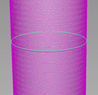
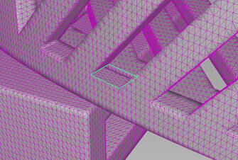
The presence of boundaries in your mesh analysis—outlined by the red lines on the model—can also imply the existence of holes in your mesh. You can visibly recognize the difference between two meshes that are not well connected –a boundary that needs to be stitched—and a hole in a mesh.
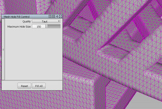
Simply select your mesh and click on the detected red boundary around the hole, which will automatically be closed. To select a filling type, divigatæe to the information window of this feature and choose ‘Taut’ for planar filling or ‘Faired’ for tangent filling.
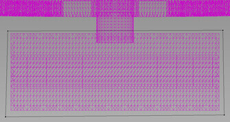
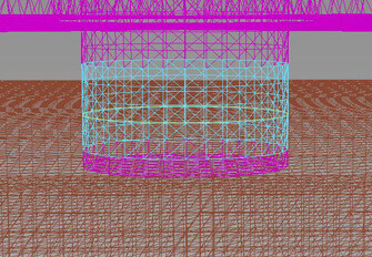
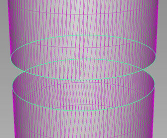
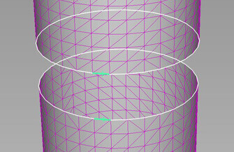
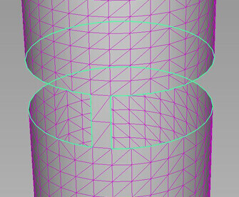
When the hole detected in your mesh is defined by two closed boundaries instead of one, like in the next example, the appropriate filling tool is called the ‘Mesh Bridge’ [Mesh>Mesh Bridge].
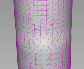
Select the mesh, and the hole boundaries will be highlighted, then proceed to select the edges of two opposite polygons which will automatically connect the holes. Repeat this operation for all the polygons’ edges that make up the boundary of the hole.
If you see no boundaries on your model but your number of components is still higher than the singular solid parts in it, it means that some shells haven’t yet been unified. Once again, the best option is to go back to your surface model and stitch your surfaces correctly. If that’s not possible, then you have to do it on your mesh.
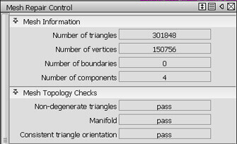
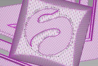
When these shells have been found, in order to be able to intersect and cut them, you must first have to divide them using the feature ‘Mesh Subset’ [Mesh>Mesh Subset]. This feature uses black dots to select the areas in your mesh that need to be divided from the rest. You can then select with this tool one of the two shells that you want to intersect and press ‘Subset’.
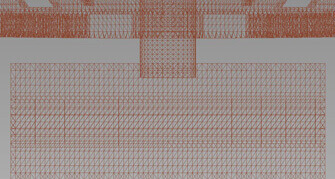
Now that you have divided the incorrect shells, you should be able to ‘Intersect’ them using [Mesh>Mesh Intersect]. Then choose ‘Cut’ [Mesh>Mesh Cut].
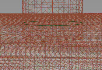
Select one shell and the cutting line just created, select which part of this shell you want to delete—the one inside your model—and press ‘Delete’. Do the same for the second intersected shell and now you will have two correct continuous shells that just need to be stitched together with the ‘Mesh Stitch’ feature described in previous sections.
If the tools and techniques just described do not fix your mesh, then trying Sculpteo’s awesome online printing automatic repair tools should be your best option. Simply export your model as .stl, as described above, upload it on Sculpteo’s website and let our repair tools do the rest for you!
The feature ‘Mesh Subset’ allows you to select precise parts on your mesh. This feature can be useful when you need to delete unwanted parts of your already meshed model such as singular faces, or need to divide it into different parts that you need to keep separated.
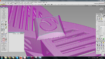
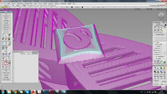
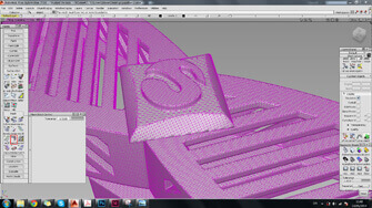
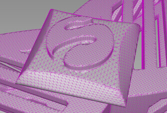
For example, if you want to delete the embossed Sculpteo logo from the model. You can do this with the active command by selecting your mesh, and
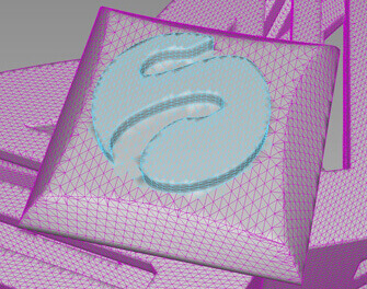
Some buttons will appear at the bottom right of the screen, choose ‘Select’ to pick the polygons—which become light blue when selected— and then click ‘Delete’ if you want to remove them permanently from your model, or ‘Subset’ to divide them from the rest of the polygons.
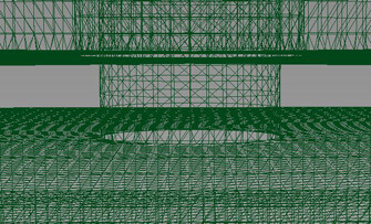
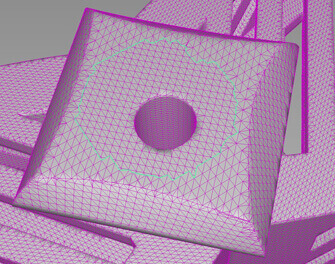
If—as in the provided example—you have deleted your polygons, a hole will then be created. Which can then be filled with the command ‘Hole Fill’