Autodesk Alias Tutorial: 3D Modeling for 3D printing with Autodesk Alias

Summary​

1. Autodesk Alias Models: Design a printable 3D file

The term manifold defines a mesh in which all its triangular edges are directly and individually connected to one another and on a surface modeling software like Alias this means that all the NURBS surfaces need to be in a relationship of continuity with one another.

This is quite obvious as can be seen from the example below of intersecting a series of extruded ( alias) surfaces in order to define or create a simple solid shape.

Also note that the excess areas on the left and right surfaces are cut away ( alias) because they are clearly not needed.

1_335px_vQaKTSm.jpg 2_335px_41kaxUC.jpg

The same principle of cutting away excess parts also needs to be applied when unnecessary surface portions which are not visible from the outside are located inside your model. This means that all unnecessary surface portions—visible or not—need to be cut off in order to prevent the creation of a non-manifold, invalid mesh.

The 2 surfaces in the example are cut at their intersection: in this way continuity between them is created, allowing them to be stitched in a later stage.

3_335px_u177GGM.jpg 4_335px_G5gUZoe.jpg

5_335px_3sboNKi.jpg 6_335px_oC4PwOw.jpg

An example of the difference that comes with modeling a character that will be 3D printed and one that will be rendered will be shown and discussed below. A model designed for rendering –with a non-continuous surface–will simply be reproduced by a rendering engine showcasing your mapped surfaces as they appear on your software viewer/workspace, but a 3d printer would recognize these non-continuous surfaces—even if they are located on the interior side of your model—as walls with no volume which are impossible to reproduce in a physical world.

In order to obtain the basic shape of the bow tie, you have to create a mirror model of the original model you created by using the mirror function: [edit>duplicate>mirror] which reproduces a mirrored image of the initial surface. The mirroring feature creates two identical parts and an overlapping surface in the middle which every 3d printer will see as an error. It’s better to avoid the creation of these kinds of surfaces while modeling or to delete them when detected, simply selecting the surface and pressing “Canc”.

7_335px_utts17D.jpg 8_335px_VxOPf7f.jpg

Now that the main body of the model has been created, you can now proceed to hollowing its interior for the 3D printer.

There are several reasons why digital models for 3d printing should be hollow but the main reason is the amount of material that will be used to produce the model. In 3d printing—unlike other production techniques— the cost of fabricating an object is not dictated by the complexity of its shape, but by the amount of material that is required to produce the design.

Therefore, making your object hollow will positively affect the manufacturing cost of 3D printing, by decreasing it to less than 60/70% of its initial cost. Another important reason to design a hollow model, is keeping your product lightweight if that’s a property you are aiming for.

But just hollowing your model doesn’t affect your product, if the hollow part is not connected to the outside through at least two holes. The reason is that “unprinted” material would be trapped inside your model if an escape passage isn’t designed.

The Sculpteo online uploader has recently been enriched with automated hollowing featurethat allows you to handle the hollowing process online. This feature automatically generates the inner shell of your model letting you simply choose the required hole positions on your model. You can upload your 3D file and try it now.

In many examples of successful 3d printed models, we have seen designers take advantage of the production driven restrictions associated with creating hollows or cavity patterns along a model surface which increases its aesthetic beauty while reducing the amount of material and therefore the production cost.

Next, we shall see how a patterned hollow can be made with Alias.

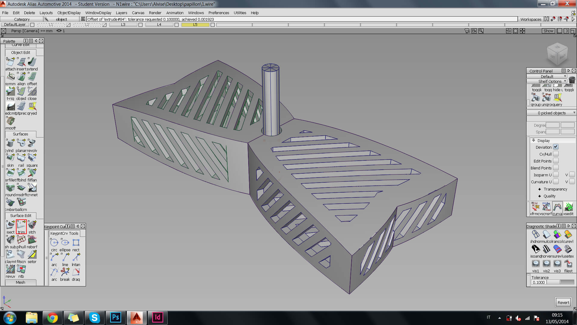
To design a hollowed pattern, you need to start by drawing a series of parallel lines that will be projected ( alias) on the surfaces of your object, which will then be used to cut ( alias) the surfaces and create patterns on them.

You must also take care that the thickness of the stripes you create are not lower than the minimum wall thickness for the Plastic material, which has been fixed at 0.8 mm before designing your model. Also note that, having an accurate knowledge of your model’s dimensions before creating them eliminates future dimension problems that may occur while printing on sculpteo.com because reducing dimensions directly on sculpteo.com negatively affects the entire model.

Anyway, a stick made with this material is rigid once it’s approximately 2 mm in thickness (check about Sculpteo’s plastic material page for more information).

9_335px_gG2DAzy.jpg 10_335px_mHL3JkD.jpg

After this operation, your model will lose its volume, so you need to add extra thickness by offsetting ( alias) all its surfaces.

The feature ‘offset’, located under the ‘object edit’ tab of the palette window, allows you to choose the distance for the new surface that has been created from the original one. Next, you should set a thickness of 1.55mm that would ensure the appropriate rigidity of your model, (assuming that it will be printed using Sclupteo’s Plastic material). When all your surfaces are offset, you then need to close the volume by connecting them using ‘skins’ surfaces ( alias).

11_335px_W48gox7.jpg 10_335px_mHL3JkD.jpg

The final shape of the bow tie’s body has been defined and the next step is to enable it to spin on a pivot when attached to a shirt and in order to do that you must create an interlocked component. This leads to the concept of ‘clearance’ and its importance to modeling moving parts in 3D CAD software.

Clearance is the space between two facing component surfaces that are in a relationship of relative motion with one another. It is important to note that every material has a minimum clearance value that must be respected, and the more clearance you use the better it would be for your model.

Also note that if clearance isn’t taken into consideration, it will result in the two surfaces of the component ending up fused together after they have been printed. To know more about clearance and how they relate to printing materials, you can check our Materials page.

Note: the clearance of the plastic material to be used in this tutorial, is fixed at a minimum of 0.5 millimeters.

Next, you intersect ( alias) a cylinder with a base diameter of 3.5 mm in the center of your bow tie and then offset ( alias) , its tubular face with a distance of 0.5 millimeters, — which is the minimum value allowed by this material— to create the necessary clearance space between the cylinder and the bow tie. This means that a clearance space of 0.5mm has been created on each side of the cylinder.

13_335px_JrAAKl7.jpg 14_335px_FC2Dd0R.jpg

alias

When designing a model for printing, it is important to have a final picture of how you want the size of the printed model to be in your mind’s eye. This image would then help you determine the minimum thickness and clearance space the final object requires to function. Any designer who plans to make use of Sculpteo’s marketplace, must also ensure that their object is designed to meet Sculpteo’s minimum size for the public.

To ensure the solidity of your model and eliminate weak pressure points, you need to take care while completing the last trimming operation to check if the holes you made in the middle of your model are not too close to one another on the surface pattern that was previously created.

To be sure that you are not generating a weak point on your model (i.e. thinner than minimum material thickness) you need measure the distance between the two holes to be sure about your surface thickness.

You should use a simple ‘keypoint curve’ ( alias) , snapped to the closest faces of the two holes, and read its length on the information window.

This quick and easy method can be used every time you need to be sure about a wall’s thickness, a clearance value or any other measure on your model. In this case the space checked is acceptable, so you can go ahead with the model.

alias

To complete the second component of the model, you need to add two elements to the extremities of the pivot previously created.

This component is now made up of 3 closed intersecting figures that will generate a valid, watertight, mesh for this configuration. Nevertheless, this configuration is still not suitable to be printed as it would require a subsequent Boolean unifying operation in another mesh fixing software in order to make the object printable. With Sculpteo, technical errors that occur are automatically corrected by its algorithm but if Sculpteo’s automated repair tools can’t solve the problems, a new page that also provides more explanation about the repair tools used as well as the repair options available to you will be displayed. You can then select the exact tools you need to eliminate the errors.

Sculpteo’s automated repairs may sometimes modify your model during the repair procedure in such a way that the final product does not meet your requirements, and also, there are some errors Sculpteo’s automated repair tools cannot correct automatically such as a file having the same object in it multiple times. Which confuses automated tools for they wouldn’t know which object to select. When this occurs it is advised that you troubleshoot every error individually to find the right solution to them.

Closed intersecting elements belonging to the same component are generally called shells and to simplify the model, it is best to have each component of the model made up of just one shell. To achieve this, all you have to do is intersect ( alias) and cut ( alias cut) the unnecessary areas on these surfaces.

17_335px_5Wb6FOT.jpg 18_335px_5NbranN.jpg

19_335px_uBHPaXz.jpg 20_335px_oheeXHI.jpg

The shape of the object is now complete and what is left is embossing the Sculpteo logo on top of your model. What you need to do first in this case, is to import a vector file of the logo in a DWG or DXF format, then scale and position it as desired over the chosen surface.

Next, divide through using the ‘Cut’ feature ( alias cut) and offset ( alias offset) the shape of Sculpteo’s logo keeping in mind that the minimum height for a clear embossed detail—like a text or 3D letters— is 0.8 millimeters for a plastic material.

It is important to note that printing curved 3D surfaces can lead to inaccuracies due to resolution. So please check for more information about the plastic material on Materialspage.

21_335px_s8u5Jb8.jpg 22_335px_4FyY96F.jpg

22_335px_4FyY96F.jpg

Alias is a great and complete tool for surface modeling but lacks advanced tools for surface mapping and an obj+mtl exporter—designed for exporting 3D files in full color—, which makes it not really suitable for producing models that will be printed using Full Color material.

Surface mapping is a technique that allows you to apply textures and images to a mesh, and .obj plus .mtl is the file format that permits you to upload this kind of model, with their relative textures, on Sculpteo’s website. Note that Sculpteo also accepts wrml file formats (check all the formats Sculpteo accepts).

Surface mapping can be done with other powerful CAD software applications such as Autodesk 3d software, 3D Studio Max, and also with the free Blender software.

Finally, the shape of the object should meet your expectations or requirements and we should be ready to prepare a printable mesh of this model.

The model that has been created so far is not yet ready for a 3D printer, and the reason is that it speaks a language alien to a 3D printer. So far, you have used Nurbs to define shapes but a 3D printer needs polygons made of faces, vertices and edges in other to understand a shape. Therefore, before meshing your 3D model it is recommended that you stitch all the surfaces together by using the ‘shell stitch’ feature ( alias
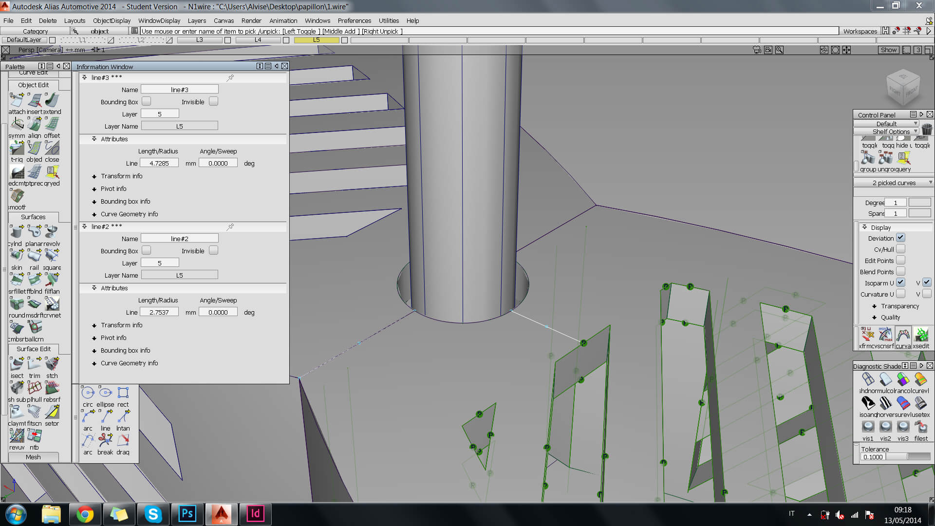
) located in the ‘Surface Edit’ tab.

This will make the subsequent mesh orientation process way faster because with this command, you will be generating two shells with coherent face orientation instead of many surfaces with random orientation that will need to be updated one after the other. This will also be discussed when we orient the mesh.

alias

To create a mesh of the bow tie and generate a model made of faces, verticals and edges for exportation as an ‘.stl’ file, simply move to the ‘Mesh’ tab and proceed by selecting the ‘Nurbs to Mesh’ ( alias nurbs to mesh
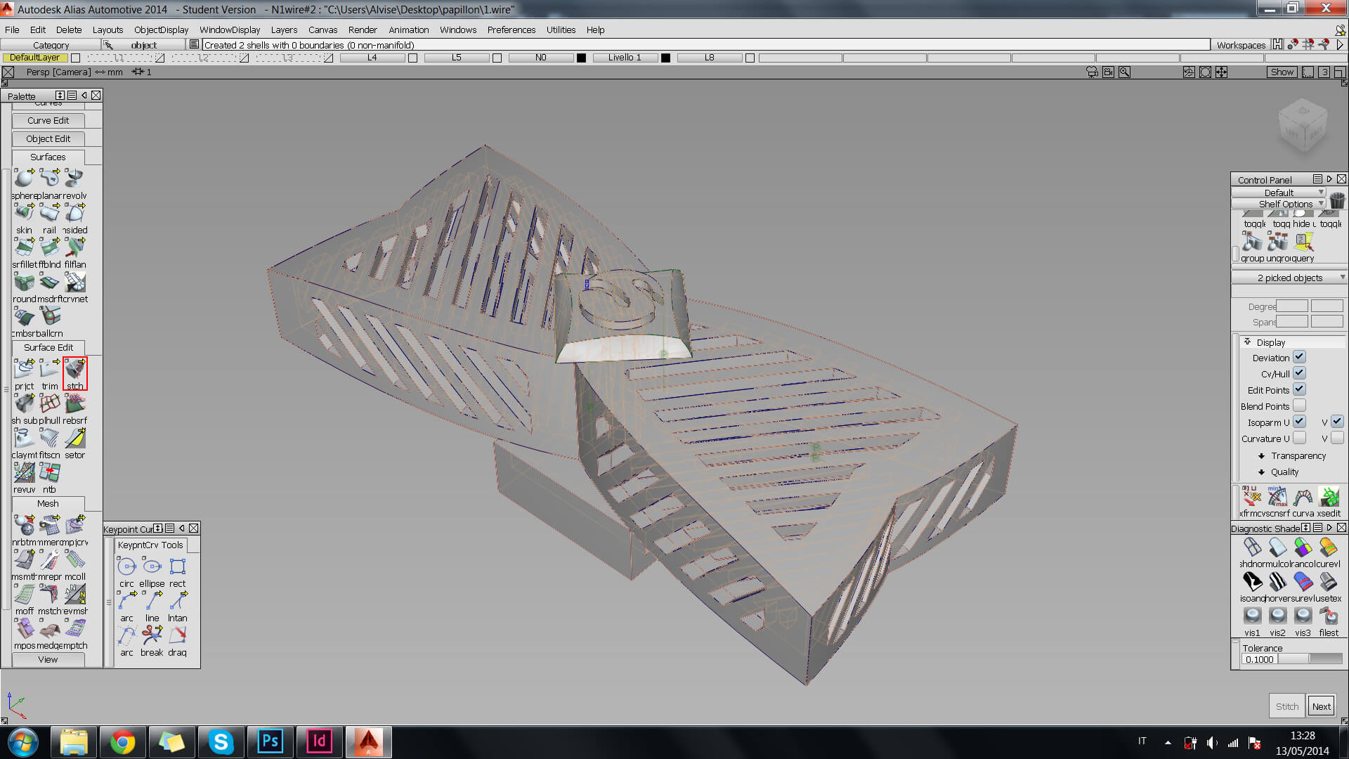
) , feature and apply it to the whole model.

25_335px_EZNWsRd.jpg 26_335px_sdUuUzx.jpg

It is important to understand that the surface quality of a printed product is determined by a number of factors which include:

  • The quality of the designed mesh for the model
  • The number of polygons in a model
  • The resolution of the 3D printer

When dealing with polygons and the quality of a product it is important to know that the number of polygons in a mesh directly affects the quality of the final product. While Sculpteo accepts models with up to 1,000,000 polygons, anything over 250,000 is generally unnecessary and will just make your model more difficult to work with. To learn more about resolution, simply check our Materials page.

On Alias, the density of your mesh can be controlled by the ‘Maxedge Length’ value found on the ‘Nurbs to Mesh’ window with a default setting of 5. For this model, the Maxedge length was moved to 0.5 in order to obtain a denser mesh. It is also advisable to tweak your settings to learn more about mesh densities.