 Connect with Google
 Connect with Facebook
Adjusting Scale and Units of Measurement
By default, Blender uses an inherent system of measurement which is not based on a measurable unit. However, as the object you will be designing will be physically manufactured, it’s important to define a unit of scale. To accomplish this, head to the “Properties” bar and select “Scene” which is represented by a small sphere, cylindar and light. There you will find measurement options under “Units” — choose “Metric”. By default, one “Blender” unit is equivalent to 1 meter. The “Scale” parameter allows you to raise or lower that equivalence globally. You’ll find the size of the object in the object’s properties (found by typing ‘N’).
.jpg")
Activating Addons
Certain Addons will be used during this tutorial and it will be important to turn them on. To do this, go into User Preferences (Ctrl+Alt+U) and into the “Addons” section. From there use the search function to find the necessary Addon.
Addons to search for and Activate: “Looptools” and “3D PrintToolbox”
To keep these Addons activated by default, click on “Save User Settings”.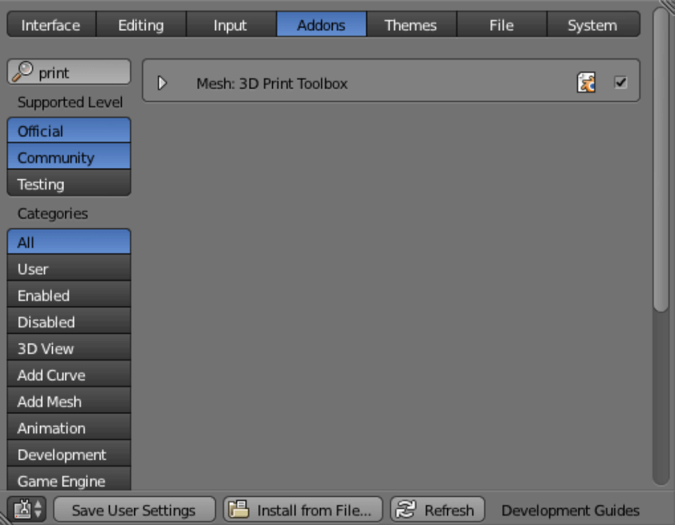
Essential Tips for Creating a printable 3D Model
When modeling for a 3D print, there are a couple rules that you’ll need to follow to ensure that your file will be printable. Those hints are listed in this section.
- Make a Manifold Model
To explain the concept of a manifold model, we will use the example pictured below. The 3D model on the left does not consist of a volume, but instead only a series of surfaces which are either a) not closed or b) lacking a defined thickness. This will cause an issue for many 3D printing programs as they are unable to print models that do not have a defined volume. To ensure your model’s printability, it’s important to close any holes in your model. This is possible by clicking ‘F’ to create an Ngon (or a surface with ‘N’ faces), then extruding, then click ‘Alt+M’ to unify the model. It is also possible to use ‘Ctrl+F’ and “Grid Fill” to close any holes. Often holes of this nature arise when generating a model for an animation or a video game, as a series of surfaces in one of those situations can cheat physics as per what will and will not be seen – physics can not, however, be cheated during a 3D print.
- Avoid Superimposed Surfaces
In the example below, the two surfaces form two volumes, however they have a face which overlaps. The orange area in the example consists of two surfaces which are on top of each other, which will confuse many 3D printing programs, you’ll need to delete the faces and join the two volumes in order to create a printable model. In the case of more complex geometries, a “Boolean” operation will join the two volumes and save you the trouble of doing it manually.

- Conserve Topologies while Minimizing Polygon Count
There’s no need to overdo your smoothing and subdividing, in fact it is important to minimize polygons to keep the file size down. In the example below, the Surface Subdivision Modifier is used once to attain a high quality surface. It is also possible to reduce the density of those subdivisions without losing too much of the general information of the surface using the Decimate or ReMesh modifiers as well.

- Avoid Cantilevered and Fine Geometries
It’s important to understand the physical limitations of the material in which you plan to 3D print. You must respect the minimum thicknesses for each material, such that every aspect of the model will be both printable and visible.
In the example below, you can see the top view of a beetle (top view is accessible by pressing 5 on the numpad). You can note the parts which are below 1mm (the minimum thickness for a plastic print at Sculpteo), as they are indicated in red. It’s important to keep in mind the minimum thickness for each material as you are creating your model, as each material has a different minimum thickness. Thankfully, after uploading onto Sculpteo, these parts will be automatically highlighted and our automated thickening tool can prepare the model for 3D printing. You can find more information on reviewing your file for a 3D print.

3D Modeling Tools
The inherent 3D modeling tools in Blender are numerous and vary greatly. We will present only the most commonly used tools below. For more information on all of the tools available within the software, check out the dedicated Blender wiki.
- Insert (hotkey “I”): Creates a loop around the selected faces.
- Instant extrude (Ctrl+Left Click): Extrudes selected region.
- Knife (Hokey “K”): Creates an edge loop for cutting the model.
- Bevel (Ctrl+B): Creates a chamfer on the selected part of the model – keep in mind that theses bevels will have a layered effect due to the fabrication process of 3D printing.
- Grid Fill (Ctrl+F): Packs the missing surfaces with a grid – this tool is ideal for closing empty parts of the model before your print.
- Bridge Edge (Ctrl+E): Adds missing faces between loops (this tool is most effective when the two sides of the loop have an equal number of vertices) – it is useful for joining two separate parts of a mesh.

Render Curves1 and Text Printable
With this example, we’re going to create a simple, supported, and printable text in 3D on a platform. To start, add a text object in an empty scene.

By default, the object is just one surface to which you’ll need to add a thickness. To do that, head over to the “Properties” panel, and choose “Extrude” – that will allow you to add depth to the object. The “Depth” parameter will allow you to change the depth of the text more precisely, if need be.

As the letters are separate, we need to create a support using a Bezier Circle. In the BezierCurve tab, choose the “2D” option and play with the thickness of the stand along side the text to your optimal parameters.

With your desired geometry, its time for the preliminary export functions. As Blender only exports polygons, you must convert the model into a singular mesh before you can correctly export it. Use “Alt+C” then choose to convert the model to a mesh from the options of Curve/Meta/Surf/Text.

Repeat the operation for the text portion of the file such that it also becomes a mesh of polygons. The conversion into Mesh may generate double vertices which must be consolidated in edit mode. Using “Ctrl+V” then “Remove Doubles” will remedy the problem – and don’t forget to recalculate the faces toward the exterior (Ctrl+N).

Your object is now ready to be exported for a 3D print.
Blender Modifiers can be applied to a model in an interactive and non-destructive manner, if used correctly. These functionalities are often referred to as a “Pile of Modifiers”. The advantage of this technique is that these modifications are non destructive to the model and do not modify the model’s topology when used in Edit mode. Modifiers can be added under the “Modifiers” tab in the properties menu (on the right side of the interface by default).
Here we are going to discover how to correctly use a modifier for a 3D print
Model a single side: The Mirror Modifier
The Mirror Modifier mirrors the geometry of an object on an axis. This modifier is very commonly used and relatively simple to operate. However a few errors ought to be avoided if you’re modeling for a 3D print.
Always verify that the axis of symmetry is in the central loop of the model. Once that central loop is defined, check the “Clipping” box from within the modifier. This will block any portion of the model from crossing the boundary of the central loop. A best practice would be to put the Mirror mesh first among the list of modifiers – this will ensure that the mesh is manifold.


Again when using the Mirror Modifier, it is important to delete all of the internal faces that can be created after the duplication of a manifold mesh. As was described earlier, these faces serve no purpose and, without a thickness, they will present a problem during a 3D print.


Reducing the number of faces (Reducing File Size): The ReMesh and Decimate Modifiers
- ReMesh Modifier
The ReMesh Modifier will remodel the topology of a mesh without modifying general geometry. This modifier can be applied to a mesh that has too many faces or is too large and irregular. This problem can arise when importing a file from another program or when dynamically sculpting a model.

- Decimate Modifier
Again, when looking to create a smaller and more easily exported file, the Decimate modifier can reduce the number and the density of faces. This modifier more precisely respects the geometry of the model but is not as respectful of the topology (when compared with the ReMesh modifier).

Adding thickness to a surface: The Solidify Modifier
The Solidify Modifier gives thickness to a surface. The “Thickness” parameter determines the thickness of the object in Blender units. This tool is ideal for creating a printable model out of a series of surfaces.

Check “eventhickness” if your model has pronounced angles. This parameter will conserve a singular thickness throughout the geometry of your model and will avoid fragile areas.

Sticking one geometry to another: The Shrinkwrap Modifier
The Shrinkwrap modifier sticks one surface to another geometry. When teamed up with the Solidify modifier, it can create clothing or accessories that will be attached to a person or an object. During a 3D print this modifier is essential for creating an object which is “stuck” to another. To avoid duplicated surfaces, be sure that the offset value is “0” within the Solidify modifier.

Correcting Multishell Geometries and Auto-Intersections: The Boolean Modifier
The Boolean Modifier allows for a boolean operation to be carried out between two volumes without destroying either. This functionality is ideal for creating a hollowing hole of the object, or to delete the intersections of faces (which can cause problems during a print).
Below, for example, we used made a boolean operation in “Union” mode in order to remove the intersection of faces.


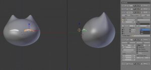
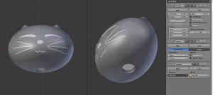
To put these modifiers to use, we’re going to create a cat’s head while using as little material as possible. We’re going to hollow out the head by adding two holes which will serve as a release for the excess powder in the model. This material reduction is only relevant to SLS and other modes of powder-layering printing.
To begin, create a sphere centered on the z and y axes.
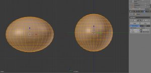 In ‘Edit’ mode, with proportions activated, displace the vertices to create a volume.
 Then, in ‘Object’ mode, add a Plane where you will design the details of the head. The following Modifiers will be necessary to create a geometry correct for 3D printing.
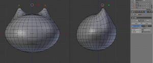
 Using simple extrusion techniques, you will be able to model different details of the face. The collection of Modifiers will allow you to create a singular volume with a simple thickness.
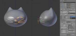 Adding the Solidify Modifier will give the object thickness. In this example we have given a thickness of 0.12cm for a head that’s 2cm in size. The Subsurf modifier will be used after the Solidify modifier such that it does not deform the ears of the model.
 In order to add a hollowing hole, add a cylinder where you would like the hole in the object. Then adding a Boolean Modifier in ‘Difference’ mode will generate a hole.
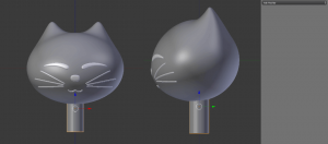 Place a cylinder using the shortcut ‘M’.
In ‘Edit’ mode, with proportions activated, displace the vertices to create a volume.
Then, in ‘Object’ mode, add a Plane where you will design the details of the head. The following Modifiers will be necessary to create a geometry correct for 3D printing.
- Mirror Modifier – duplicates the geometry on the X axis.
- Subsurf Modifier – smooths the object before a Shrinkwrap
- Shrinkwrap Modifier – activate on the sphere to adhere the geometries. Use ‘Project’ mode and check the ‘Negative’ option to project the form of the object.
- Solidify Modifier – gives the geometries a volume. Here the ’offset’ must be set to 0 so that the thickness is linked to the head.
- Subsurf Modifier – gives a second layer of smoothness
Using simple extrusion techniques, you will be able to model different details of the face. The collection of Modifiers will allow you to create a singular volume with a simple thickness.
Adding the Solidify Modifier will give the object thickness. In this example we have given a thickness of 0.12cm for a head that’s 2cm in size. The Subsurf modifier will be used after the Solidify modifier such that it does not deform the ears of the model.
In order to add a hollowing hole, add a cylinder where you would like the hole in the object. Then adding a Boolean Modifier in ‘Difference’ mode will generate a hole.
Place a cylinder using the shortcut ‘M’.
Your object is ready to be exported for 3D printing.
Often when preparing a file for 3D printing, you may use multiple 3D modeling programs. It’s common to create the base of the file in another program and then import it to Blender to add more details than would be necessary for a 3D print.
Importing by Default
Blender supports the following filetypes for import:
Files with texture and meshes:
Addons tab. Click on Import-Export and choose the Addons you’re looking to activate.
_BuRNE2p.jpg "BLENDER 1.2 (1)_BuRNE2p.jpg") Importing with Blender
Example using
Importing with Blender
Example using an .stl file:
_3LHk1C7.jpg "BLENDER 1.2 (2)_3LHk1C7.jpg")
_PlMQbDy.jpg "BLENDER 1.2 (3)_PlMQbDy.jpg") Files created in other programs often do not have the correct scale information. In this example, the file needed to be rescaled to 0.1.
Files created in other programs often do not have the correct scale information. In this example, the file needed to be rescaled to 0.1.
_Ouy4f9r.jpg "BLENDER 1.2 (4)_Ouy4f9r.jpg")
- .dae (Collada)
- .obj (wavefront)
- .fbx (Autodesk FBX)
- .x3d/Wrl (x3D Extensible 3D )
- .stl (Stereolythography)
- .3ds (3d studio)
- .ply (Stanford)
- Fichiers 2d Vectoriels
- .svg (ScalableVector Graphics)
Importing with Blender
Example using - Go to File / Import / .stl
- Choose the file from your computer
- The file is now imported into Blender
Files created in other programs often do not have the correct scale information. In this example, the file needed to be rescaled to 0.1.
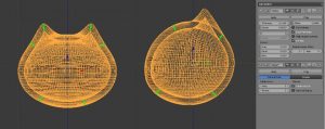
MeshAnalysis
MeshAnalysis is used to display problems with a Mesh. This tool only works in Edit mode and displays the problems a range of Blue (for lower values) or red (for higher values). If there are problems to be fixed, its important to correct all of the colored faces – the faces that do not need to be fixed will not be highlighted and will be shown in grey. You can find this tool in the properties of the 3D View (by clicking ’N’). Be careful with models with high polygon counts as the mesh analysis will take longer to process.
_BakMhJP.jpg "BLENDER 1.2 (5)_BakMhJP.jpg")
_iVdZVY0.jpg "BLENDER 1.2 (6)_iVdZVY0.jpg")
_PsvsfTN.jpg "BLENDER 1.2 (7)_PsvsfTN.jpg")
_7cT9pOv.jpg "BLENDER 1.2 (8)_7cT9pOv.jpg")
_2ePfhVJ.jpg "BLENDER 1.2 (9)_2ePfhVJ.jpg") PrintTool Box Addon
To learn how to activate this Addon head over to the preceding section that explains “Activating
PrintTool Box Addon
To learn how to activate this Addon head over to the preceding section that explains “Activating Addons ”.
This Addon can be accessed by tapping ’T’ on the 3D viewer, this Addon provides a couple extra features that are not included with MeshAnalysis. It has the advantage of directly selecting the areas that pose problems and possesses finer analysis tools. This tool also has the advantage of working in wireframe mode with activated Modifiers. In edit mode, simply enter the desired settings and click “Check all”. The tool will detect any problems and provide a general error report.
Example: for parts of a human character, the PrintTool Box add-on will select the exact parts of the model that need to be fixed.
_JxDgmIW.jpg "BLENDER 1.2 (10)_JxDgmIW.jpg")
- Overhang
- Intersections
- Thickness
- Distortion
- Sharp Edges
PrintTool Box Addon
To learn how to activate this Addon head over to the preceding section that explains “Activating
- Volume: calculates the volume of the model
- Area: calculates the surface area of the model
- Solid: indicates if the model is non-manifold and if the faces are oriented in the correct direction. It also gives you the ability to automatically select and deselect any problem vertexes.
- Intersections: indicates any crossing faces
- Degenerate: displays any faces that have no size and that may present a problem for some programs
- Distorted: displays any faceless planes
- Thickness: indicates any places where the thickness is lower than a predetermined value
- Edge Sharp: shows any edges that are too sharp
- Overhang: shows the faces for which the angle as compared with the base is less than a predetermined value
- Check All: checks all of the above parameters
- Isolated: deletes any vertices without a volume
- Distorted: deletes any faceless planes
- Scale to Volume: modifies the scale of an object according to a predetermined volume
- Scale to Bounds: modifies the scale of the model according to a maximum length
- Export Path: exports only the selected area. These two buttons allow you to add the mesh to the export and the texture information of the model for multicolor 3D prints.
Export for a monochrome 3D print
The most common format for a printable monochrome 3D model is .stl (Stereolithography).
To export
_qYYgrmi.jpg "BLENDER 1.2 (11)_qYYgrmi.jpg")
Select the folder where you’d like the file to be exported and check the boxes of the modifiers you’d like to use. Name the file then export.
_eZ6hnqF.jpg "BLENDER 1.2 (12)_eZ6hnqF.jpg")
Export for a multicolor 3D print
- .obj Files
The most common format for a printable multicolor 3D model is .obj, as it defines both the geometry and is accompanied with the textures whose location is defined on the model using
For the multicolor information to be interpreted, an image file must be included with the file, which will be used as the texture of the 3d model.
To export a 3D model as
_nvyp2tH.jpg "BLENDER 1.2 (13)_nvyp2tH.jpg")
In the exporting options, choose “selection only” and choose “copy” in path mode. This will ensure that all of the files you’ll need to for a successful multicolor 3D print will be included in the location you’re creating. After that, name the file and click “Export OBJ”.
_jBqUFgV.jpg "BLENDER 1.2 (14)_jBqUFgV.jpg")
- .dae File Format
The Collada format can be a good alternative to .obj if you have problems during the export. With .dae files, the UV mapping texture and material geometry information are included in the file. As for .obj files, texture files are needed and they need to be zipped with the .dae file. The difference is that there is no need to add a .mtl file.
To export in .dae choose the model you’d like to export and go to File / Export / Collada.
_0DQME8Q.jpg "BLENDER 1.2 (15)_0DQME8Q.jpg")
In the export options, choose “selection only” and choose “copy” in path mode. This will ensure that all of the files you’ll need for a successful multicolor 3D print will be included in the location you’re creating it. After that, name the file and click “Export COLLADA”.
_o96BUjL.jpg "BLENDER 1.2 (16)_o96BUjL.jpg")
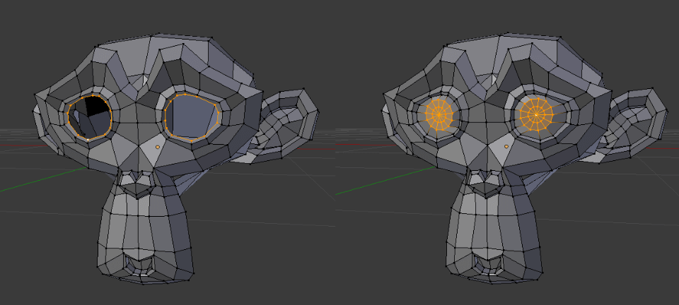
To select the edges of non-manifold mesh, use the Addon “Print Tool Box” or select “No manifold” in edit mode.
_KSr8fQB.jpg "BLENDER 1.3 (1)_KSr8fQB.jpg") Then by hitting the F key, the empty parts will be filled automatically. Warning: this mode may create Ngons (faces with more than four vertices).
Then by hitting the F key, the empty parts will be filled automatically. Warning: this mode may create Ngons (faces with more than four vertices).
_rywmpNQ.jpg "BLENDER 1.3 (2)_rywmpNQ.jpg") It is possible to use the function GridFill where the vacuum portion will be formed by an even number of vertices.
It is possible to use the function GridFill where the vacuum portion will be formed by an even number of vertices.
_mGC0tQo.jpg "BLENDER 1.3 (3)_mGC0tQo.jpg")
Then by hitting the F key, the empty parts will be filled automatically. Warning: this mode may create Ngons (faces with more than four vertices).
It is possible to use the function GridFill where the vacuum portion will be formed by an even number of vertices.
The non-planar faces are generally quads (faces with four edges) or Ngons (faces with more than four edges) that have too much internal angle. These faces are often seen as non-printable by 3D printing software. Use the add-on “3D printtoolbox ” to select the “Distorted” faces. Then in Edit mode, in the header of the 3D viewer, use Mesh / Clean up / Split non-planar faces. Blender will generate triangles instead of quads. Please note that this action is irreversible and changes the topology of Quads to tris.
_qAR1gwG.jpg "BLENDER 1.3 (4)_qAR1gwG.jpg")
Isolated vertexes and faces ought to be excluded from the model. These are often forgotten remains of a model which was not finished. They need to be deleted because they are volumeless parts of the model, which are not printable. To remove the isolated pieces of the mesh, use the add-on “3D PrintToolBox”, click the “Isolate” button, then “Cleanup”.
_oVOaxOl.jpg "BLENDER 1.3 (5)_oVOaxOl.jpg")
Sharp bends in 3D printing are problematic because they create parts that are too thin to be printed. After you locate an acute angle in Edit mode, it is possible to use Addon 3D PrintToolBox to select the problem part. Then use the “Smooth” tool in the Special menu (shortcut W).
_sjQQ6xR.jpg "BLENDER 1.3 (6)_sjQQ6xR.jpg")
When a part is too thin to be printed, it is possible to thicken the general size of the object to thicken the problem zone.
If you’re looking to thicken just the part of the model that is too thin, there are a couple of solutions that are possible. Most of the time, a Scale along the normal with edit mode activated will suffice.
Here’s an example of a hand with fingers that are too thin to print.
_w0NnoGB.jpg "BLENDER 1.3 (7)_w0NnoGB.jpg") It is also possible to “stick” the parts that are too thin to a thicker geometry. You must fuse the geometries such that they will not create superimposed surfaces, however.
Example of a hand stuck to a character.
It is also possible to “stick” the parts that are too thin to a thicker geometry. You must fuse the geometries such that they will not create superimposed surfaces, however.
Example of a hand stuck to a character.
_dRITCb0.jpg "BLENDER 1.3 (8)_dRITCb0.jpg")
It is also possible to “stick” the parts that are too thin to a thicker geometry. You must fuse the geometries such that they will not create superimposed surfaces, however.
Example of a hand stuck to a character.