Connect with Google
 Connect with Facebook
Using OpenSCAD for 3D Printing is AWESOME
Posted By admin on Sep 12, 2015 | 0 comments
By now it’s really not difficult to see the immense potential that 3D printing offer to us and these days more and more people are eager to jump on board and benefit with this amazing technology. As often happens with new technologies, it requires some learning on the user’s side to take full advantage of all these new tools available. In the case of 3D printing the first challenge commonly comes when we need to create a digital representation of our idea, i.e. the 3D model that computers and printers can understand.
Although having a wide range of alternatives is always welcome, choosing the right one among so many options can be overwhelming. This decision will obviously depend on what we are aiming to design, how much time and money we are willing to invest into it and, of course, personal taste. Having said this and knowing that no tool will work for everyone, I would like to tell you about an amazing and extremely powerfull free alternative which is particularly efficient to create mechanical objects and all sort of things excluding organics forms (which is not even impossible, but it will get trickier).
OpenSCAD is a free software that allows you to create solid 3D CAD objects. Its main difference with most other options out there, and also what makes it so efficient for certain types of objects is that this is not an interactive modeller. Instead, you code your object as a list of easily readable instructions than are then compiled by OpenSCAD to output the 3D file you need. But wait! ..you may be thinking you have to be a professional programmer or an IT expert to handle this kind of 3D modelling and this definitely not the case! ..it is the goal of this post to encourage you to discover that by yourself!
Before going to the specifics it’s useful to know the two main methods in use by this tiny 14MB software:
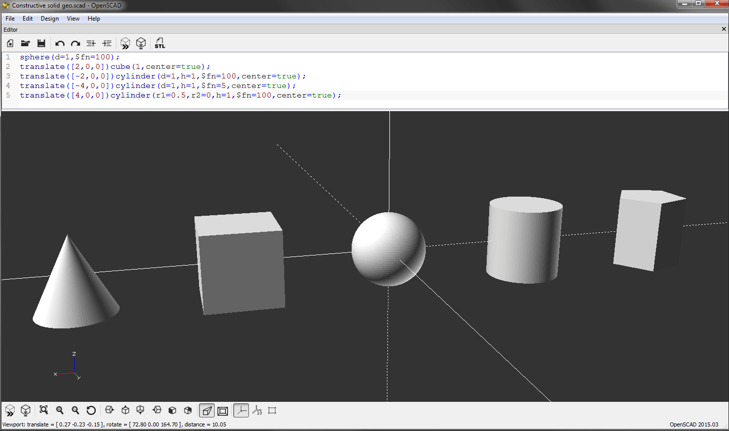
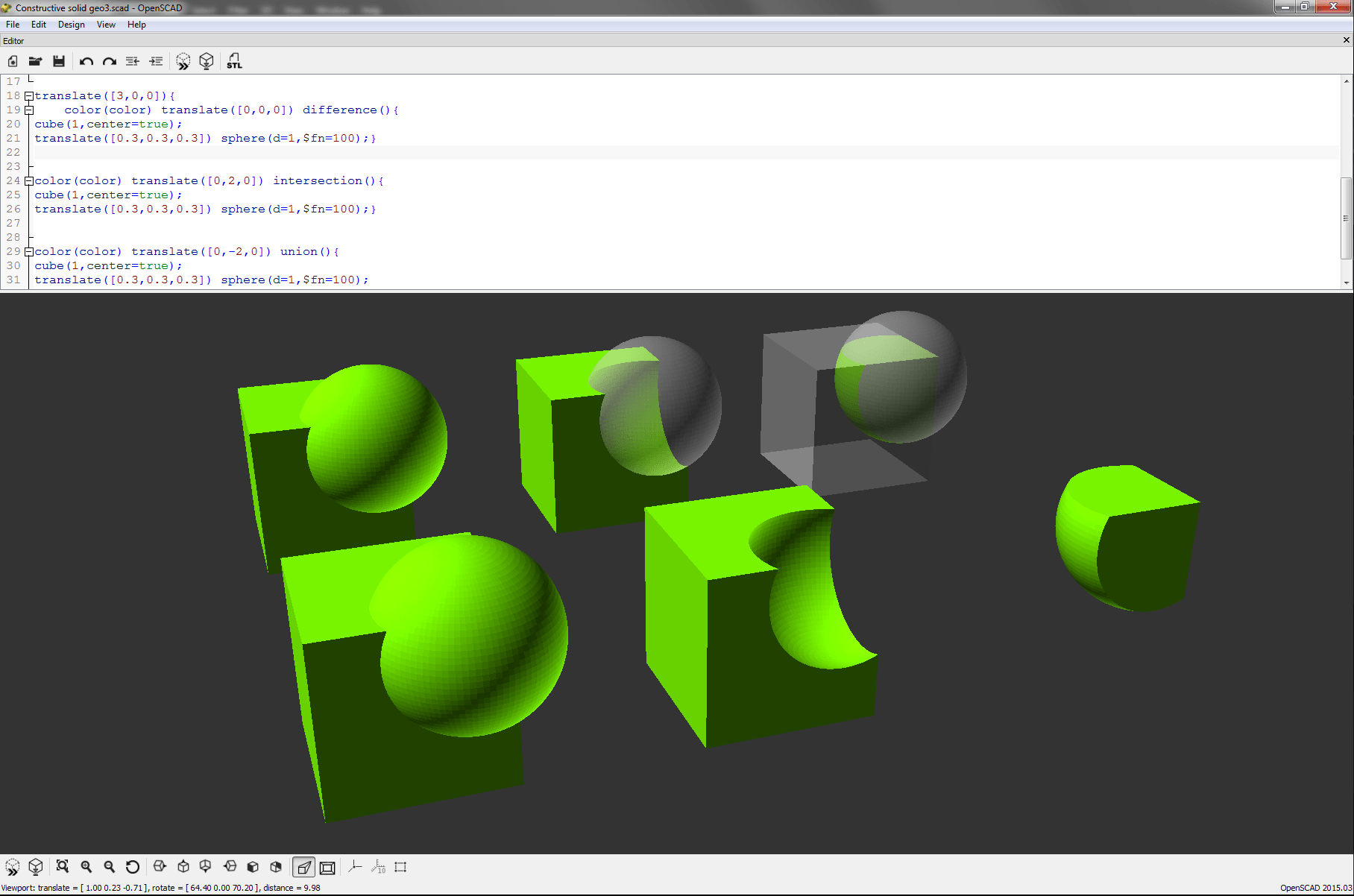
- Constructive solid geometry: Using a set of primitive objects (typically cuboids, cylinders, prisms, pyramids, spheres, cones) and Boolean operations (union, intersection and difference) it allows us to create seemingly complex objects, which are in reality just a cleverly combined group of these primitive shapes and operations.Set of 3D primitives
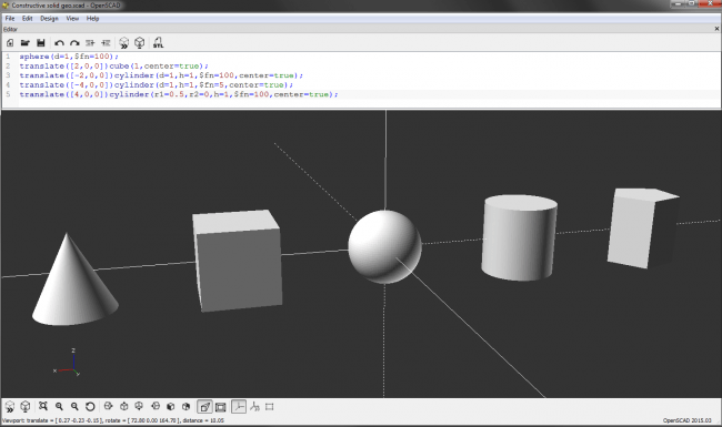 Example of union, subtraction and intersection of a cube and a translated sphere
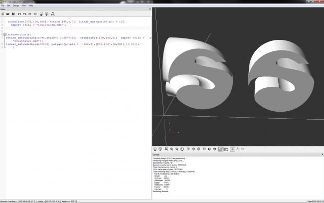
- Extrusion of 2D outlines: Allows us to create 3D objects by extruding (both linearly or rotationally) bidimensional shapes. These shapes can be primitive 2D shapes analogous to the 3D objects (like circles or rectangles) as well as combinations of it, text or even imported shapes using DXF files (another CAD file format).Example of linear and rotational extrusion of a shape imported from a DXF file

The procedure to create an object is just to start with one or more of the primitive shapes/objects available and apply them a series of simple transformations and/or operations with other objects until we get to the desired object. All off this also comes packed with a few useful capabilities like
- mathematical expressions, we can easily properties of several objects linked in complex way thanks to OpenSCAD’s built-in math operations.
- functions, specially useful for frequently used calculations.
- modules, to reuse parts and/or transformations while making your code cleaner and easier to read.
- variables, that allow you to easily tweak aspects of your model down the road without having to change the code and some other advanced features.
Given the very same nature of this way of modelling, OpenSCAD does a great job when precision design is required, when certain parts of the model need to be modified repeatedly during the design process (use variables!), or when your design is based on multiple iterations of similar objects (which can be converted into a module and called as many times as necessary).
All in all OpenSCAD is a free and friendly scripting 3D modeling software, even without previous programming experience.. but.. you wouldn’t believe this without a few examples right? So let’s create something..
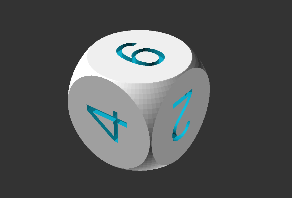
First thing to do, just as you would normally do with any other modelling software is trying to imagine a build strategy for the desired object, in this case, a simple dice.
We will first create its body consisting on a cube with rounded edges. One simple way to do this would be intersecting both a cube and a sphere, trimming in one single step all the corners of the cube.
// this is a comment
// we define the cube’s size here to have it to hand..
sidecube=20;
diametersphere=20*1.4;
// the sphere’s size as a function of the cube for easy scaling
intersection() {
    sphere(d=diametersphere, $fn=100); //we created a sphere
    cube(sidecube,center=true); //and now a centered cube
}
Pay special attention to the semicolon at the end of each statement to avoid errors when compiling. By adding center=true to the cube function we force it to be exactly on the coordinate origin instead of being entirely on the positive octant (default option). The default units are mm and the special variable $fn=100 defines the number of facets used to generate an arc, which translates into a smoother sphere than if we used a lower number. This special variable also applies to any other curved surface like extrusions, cylinders, etc.
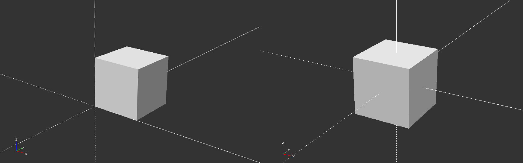
Default positioning on the left, center=true on the right.
Next, since we want engraved numbers we will “subtract” them from the main body. Before doing this, of course, we need to create them with the function text and place them on their corresponding side of the dice. Using this text tool will create a 2D text on top the positive X axis, but in this case the cube is centered so we will use halign = “center” and valign = “center” to align the text vertically and horizontally exactly centered with the origin. So far, even if it may look “3D” on the screen we only have 2D text so our next step is to extrude it to a 3D object. Next comes a translation along the vertical axis to place the 3D number on the upper face of the dice, from where we will rotate it along the X and Y axes to its final position for each number. All this process could be done in many ways but a simple “manual” version would be:
rotate([0,0,0])   translate([0,0,9]) linear_extrude(height=2)
text("1",size=10, halign = "center", valign = "center");

rotate([0,180,0]) translate([0,0,9]) linear_extrude(height=2)
text("6",size=10, halign = "center", valign = "center");

rotate([90,0,0]) translate([0,0,9]) linear_extrude(height=2)
text("2",size=10, halign = "center", valign = "center");

rotate([-90,0,0]) translate([0,0,9]) linear_extrude(height=2)
text("5",size=10, halign = "center", valign = "center");

rotate([0,-90,0]) translate([0,0,9]) linear_extrude(height=2)
text("3",size=10, halign = "center", valign = "center");

rotate([0,90,0])  translate([0,0,9]) linear_extrude(height=2)
text("4",size=10, halign = "center", valign = "center");
Right after before the rotation all the lines are basically the same (aside from the number) and it’s only that final rotation that spreads the numbers on each side of the main body.
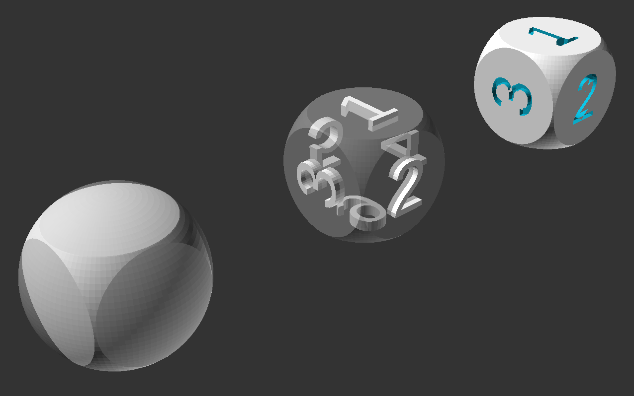
The final step then, will be simply to subtract all these numbers form the body. This is done using the difference operation that will subtract every object listed after the first one to that very same first object. The final code will be:
sidecube=20;
diametersphere=20*1.4;

difference(){
intersection() {
sphere(d=diametersphere,$fn=100);
cube(sidecube,center=true);
}

rotate([0,0,0])   translate([0,0,9]) linear_extrude(height=2)
text("1",size=10, halign = "center", valign = "center");

rotate([0,180,0]) translate([0,0,9]) linear_extrude(height=2)
text("6",size=10, halign = "center", valign = "center");

rotate([90,0,0]) translate([0,0,9]) linear_extrude(height=2)
text("2",size=10, halign = "center", valign = "center");

rotate([-90,0,0]) translate([0,0,9]) linear_extrude(height=2)
text("5",size=10, halign = "center", valign = "center");

rotate([0,-90,0]) translate([0,0,9]) linear_extrude(height=2)
text("3",size=10, halign = "center", valign = "center");

rotate([0,90,0])  translate([0,0,9]) linear_extrude(height=2)
text("4",size=10, halign = "center", valign = "center");
}
There are also a few extremely useful tools to make the visualization of several objects easier. For instance, quite often we are working on one part and we don’t need other parts to be there (but we can’t just delete them!), so thankfully OpenSCAD allow us to render any part transparent by adding percentage character “%” at the beginning of that object’s line. Also we can just hide it using an asterisk “*” or even show only a specific object by using a “!”.
Then, this code:
$fn=50;

translate([0,0,0]){
cube(1);
sphere(1);
}
translate([-3,0,0]){
%cube(1);
sphere(1);
}
translate([-6,0,0]){
*cube(1);
sphere(1);
}
Will result in:
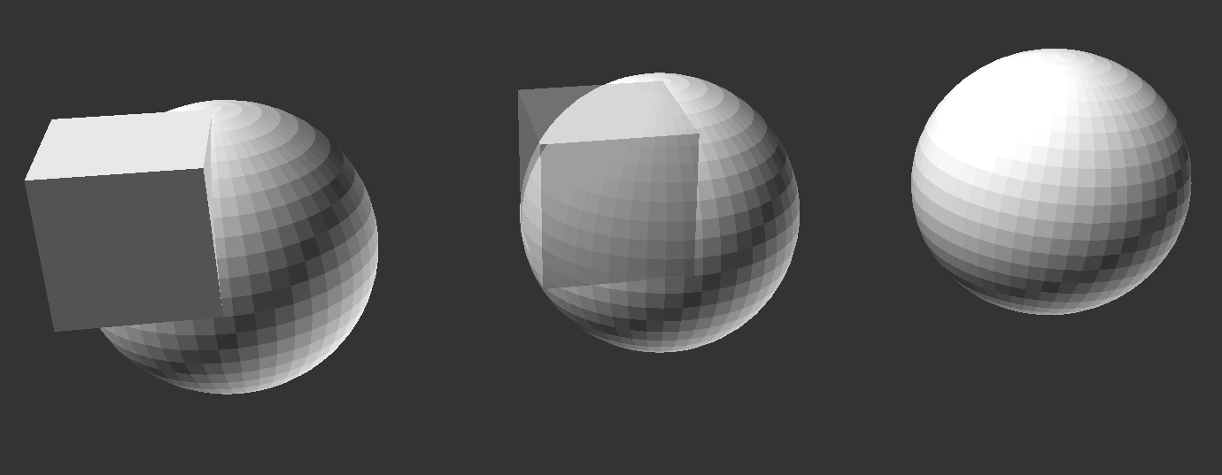
From left to right: All shown, using the “%” modifier on the cube and lastly “*” on the cube too.
Once we are satisfied with our design, is just a matter of waiting for it to render (shortcut:F6) which depending of the model could take anything from a few seconds to several minutes, and exporting you design as a STL file, which is one of the most popular 3D file formats currently in use. Another advantage of OpenSCAD and script-based modelling in general is that you can also share or save your design as a native .scad file which is usually thousands of times smaller than the same design as a STL file.
After some practice it will be natural to remember most instructions and how to use it, but both the beginner as well as the experienced user will appreciate the official cheatsheet for quick access to all the functions available.
I hope this post provides you the necessary motivation to give OpenSCAD a worthy try. At Sculpteo we think that this is a pretty awesome piece of software so not only we support direct uploads of SCAD files, much faster than uploading a standard STL file, but we also give you the possibility to change your file’s variables online so you can modify your design without needing to export a new file and upload it every time!
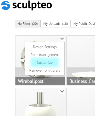
Once your file is online, you can find it on your gallery and tweak it in any way you want under the Customize section. Remember to comment above the variable declaration to turn it into a parameter as explained in the links above. You can also specify the range of the parameter by commenting it just by the variable declaration.
For example
// angle in degree
AX=90; // [45:90]
or
// angle in degree
AX=90; // 30,45,60,90
Finally, if you do decide to turn real one of your designs, bear in mind the design guidelines for 3D printing (check our ebook! Design_Guidelines_for_3d_Printing) to avoid multishell or fragile objects. Also remember that there is a minimum size for every 3D printer, and you can use our solidity check tool if you are not sure about the size of your design.
So.. what are you waiting for? Go for it, download OpenSCAD now here and start coding your own amazing designs! Get the dice we just designed here:
Dice 924bytes
or if you feel confident you can check a more compact version of the same dice:
You can also learn about some other cool features of OpenSCAD reading this cool post by Jeremie Francois.
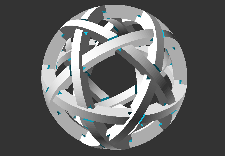
As a bonus you can play around with this other design which uses a module for a repeated part and see all you can do with only 20 lines of code:
SCAD: Wireball