 Connect with Google
 Connect with Facebook
Prototype your Gear Set with 3D Printing
Posted By Arthur Cassaignau on Mar 9, 2016 | 0 comments
Gears are probably one of the most common mechanical parts that one needs to build when creating a complex mechanical system. While the function itself is easy to understand, making a gear set that works is another thing. It requires some basic knowledge of how gears are moving together, and for the most complex systems, a quick look at the different typologies of gears might save you some time. Packed in this post, you’ll find some useful resources to test a gear set and turn them into a 3D printable system of gears.
A while ago on our blog, we published a Customer Success story about Pierro Astro, a French company producing and selling telescopes, astronomic glasses, and accessories that allow users to observe and take pictures of the sky. In this blog post, the founder at Pierro Astro explains that they’re also developing their products when there is no on-the-shelf offer to fit their needs. Notably, they used 3D printing to first prototype and then produce different gear sets that were used to focus Schmidt-Cassegrain reflectors with extreme precision.
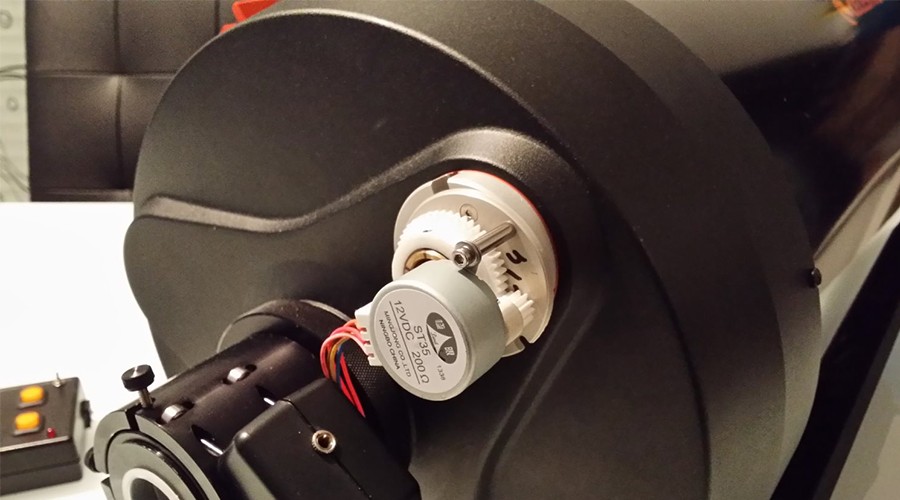
Behind the motor, the set of gear used to focus Schmidt-Cassegrain reflector has been entirely 3D printed
So how do you achieve the same kind of gear sets?
First thing first, let’s take a look at how a set of cogwheels should be designed to make sure they can move together as a system. A useful resource for that is a tutorial published on Instructables by Tomdf where he explains how he designed different sets of gears and the basic notions that you should know to develop yours. While there are many (really many) parameters that let you create gears with the least amount of friction, Tomdf reduces the number of variables to three of the most important:
- The Center Distance (CD)
- The Pitch Diameter (PD)
- The Outside Diameter (OD)
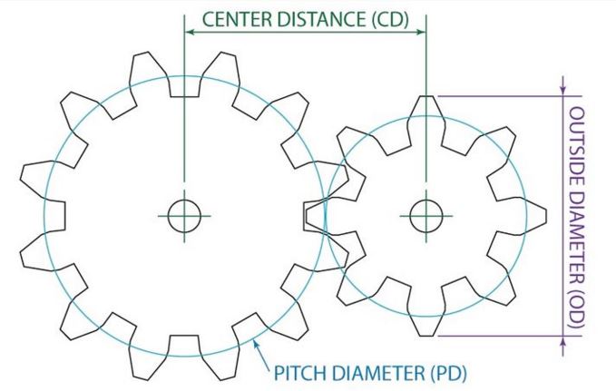
This drawing shows the three most important parameters of gear: the Center Diameter, the Pitch Diameter, the Outside Diameter
Prototype your gear sets in 2D using Gear Generator
Looking at the drawing above, it’s quite simple to understand how this all works together with those three variables. Though if you don’t want to make any calculations, there is a pretty simple way of creating your system thanks to a resource available online: the Gear Generator. This resource is quite useful because it breaks down all the traps you could fall into when designing a set of gears and lets you create your own and even verify whether it’s going to turn or not. To understand how it works, we’ve prepared a short video tutorial to see how you can prototype a gear set in 3D and then export the .svg files of the each gear.
Gear Generator simplifies the maths behind making a gear set and makes the different calculation for you. It’s especially useful because it will calculate the right Center Distance as well as the outside diameter. Though you remain in control of other key factors like:
- Number of teeth
- The Pitch Diameter (useful if you’re gear set functions inside another system that requires large or small gears to move)
The interface of the website is quite simplistic and lets you add or remove gears to the set as you wish. For each gear, you’re adding you’re able to select the parent gear it needs to be “attached” to and define is both the parent/child gear are sharing the same connection axis. It’s a useful feature if you’re willing to connect multiple gears to the same axis. The connection angle allows you to set up the disposition of the gears towards one another.
Once everything is in place, you can animate the set and even define the RPM so that you don’t wait too long to see it moving. To download the drawing of each gear, you’ll just need to select the right cogwheel and click and the “Download SVG” button. Now it’s time to turn these .svg files into printable .stl using Blender.
Using Blender to convert a .svg file into a 3D printable model
After creating your set of cogwheel using Gear Generator, you’ll have some .svg files to that still need to be turned into a printable .stl. To do that, we are using Blender. We’ve created a short video tutorial showing how to use Blender to convert a .svg file into a .stl (3D printable model). The operations shown in the video don’t require any particular training on Blender and are accessible to anyone. There is no audio in this video (for now), for a better understanding of the whole process you can read the instructions below.
In that order, there are in total 19 operations to go from the .svg to the .stl file.
- Click on the start-up model that already loaded when you open Blender. For that, just click on the model and hit “delete”.
- In the top bar, go in File > Import >Scalable Vector Graphics (.svg). Your file is imported into the 3D scene.
- Scroll with the mouse wheel in the scene to find the imported file. It will be added next to the origin of the scene. Note that when you keep the pressure on the scroll wheel, you can rotate around the origin of the scene.
- In the right column, select the curve corresponding to the cogwheel itself and move it aside from the other curves.
- You’re now able to select all other curves that were imported and that won’t be used. To select them all, click on Ctrl and with the right click of the mouse, choose the zone where they all are. Delete them.
- Replace the gear drawing at the origin of the scene (it’s useful for the next steps). To do that hit the small “+” sign next to the right column and enter the value 0 for the x,y and z of the location. After that use Shift + Ctrl + Alt + C to set the geometry to the origin of the scene.
- Now extrude the shape (timeline 0:54 in the video)
- Set the correct size for the gear in Dimension. Particularly the proportion so that your gear will fit your system.
- At this point, the model looks like a solid, but it is still only a curve in Blender. It’s problematical if you’re willing to remove a volume in the gear’s center to create the axis that will be used for to rotate the part. To transform it into a mesh, you can use the Alt + C shortcut > Convert to Mesh from Curve. It’s now a mesh.
- Now what we want to do is to create a hole right in the middle of our first mesh for the rotation axis. Clic on Add > Mesh > Cylinder.
- Set-up the size and location of your new Cylinder using the right column. Make sure that it intersect with the gear and that the diameter of your cylinder is the one of your future axis (make it proportional to the rest of the gear).
- The next step is called a Boolean operation. It will let us “subtract” one volume to another. Make sure you select the right volume (in this case our first mesh) and still in the right column click on the small wrench icon > Add a modifier. Select Difference for the operation and the object on which you apply it (here Cylinder). Hit Apply.
- You can now delete the Cylinder. Select it and hit delete.
- The last operation can also sometimes be useful to make sure that you’re newly created gear is one single volume. For that select the right object (the first mesh) and go back on the small wrench icon. Add Modifier > Generate > Solidify. Set up the correct thickness and you’ll be good to go.
- You now have a solid gear that you can export as a .stl file.
Upload your .stl to Sculpteo
Okay. It’s just one gear and not the whole set. But repeating the operation for each gear of your system will get you there. Once you have your 3D printable file, you can either print it on your personal 3D printer or use our online 3D printing service for that. Sculpteo offers you the possibility to 3D print your 3D file in more than 50 different materials and finishes. To do it, it’s very easy. Go to Sculpteo, log in to your account and follow the steps from the video below.
To create gears and to prototype complex mechanical system, we particularly encourage our customers to use our plastic material. It offers excellent mechanical properties (you can consult the data sheet of our plastic material), even if you’re willing to not only use this material for prototyping but also for your production run. You can take a look at how different customers used our service for both prototyping and production.