Laser cutting service : Design your Own Gear Mechanism
Posted By Eole Recrosio on May 3, 2017 | 1 comment
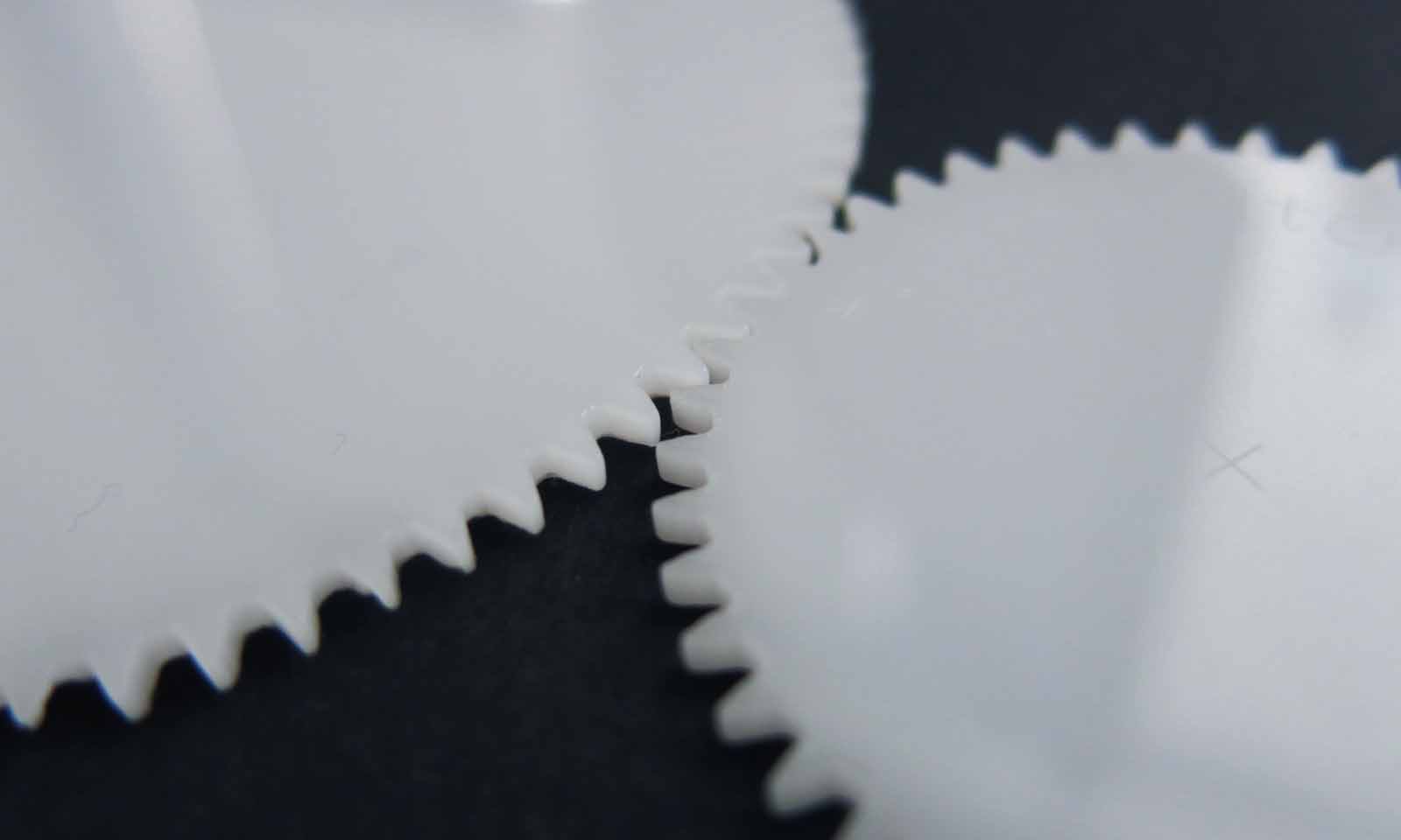
Laser cutting is a fast and cheap manufacturing technique. It is possible to use it for decorative parts with wood and acrylic but also mechanical parts with POM and metal. In this article, discover how we used this manufacturing technique to create gear mechanism. You’ll learn all you need to know before starting to laser cut gears with our POM material.
Gears, Cogwheels and mechanism
What is a gear?
A gear (or cogwheel) is a very common rotating mechanical part with teeth designed to transmit a movement
or a torque (the force applied to make the gear rotate).
Gears are used to transmit or modify the speed or direction of a power source to a moving part.
The key notions of a gear are:
- The shape of the tooth
- The angle of the transmission
- The gear ratio or velocity ratio
- The link type
- The size of the gears
- The material used
These key notions determine the application and what kind of movement you’ll obtain for your mechanism.
Type of gears and Applications
Gears are the basic brick of power transmission mechanism. It can be found in clocks, engines, optical devices or industrial scale machines. In fact, from the power engines of the biggest machines to the small gears in a watch, gears are a very useful piece of mechanism used in many sectors.
There are many types of gears depending on what you need. It can be used to change the speed of a rotational movement. For instance, a gear reducer uses a series of either planetary gears, strain wave gears or a worm screw (endless screw) to act on the initial movement.
Gears can also be used for transforming a straight movement to a circular movement for example. This principle is often used in the automotive industry for connecting rods.
Laser cutting gears that fit your needs
Usually, gears are manufactured by net shaping molding with metal or plastic powders or by traditional machining techniques. Thanks to Sculpteo’s online services, you can design your own custom gears in many materials with both 3D printing and laser cutting.
Laser cutting is a very precise subtractive method that can manufacture gears from vector files (SVG). There are several softwares and techniques to obtain a SVG file that contains your gear mechanism. On a previous article, we explained how to obtain one thanks to great online resources.
What to know before designing gears for laser cutting
When designing for laser cutting, several characteristics have to be taken into account in order to obtain a functional gear mechanism.
The first thing to know with laser cut is that it’s linked to the cutting technology. Laser cannot be oriented at an angle that’s why it is impossible to cut at an angle. The gears obtained thanks to laser cutting are spurs gears.
To learn more about the laser cutting technology, you can check the FAQ.
Size of the gear
The gear has to respect the maximum and minimum dimensions of the machine to be properly laser cut.
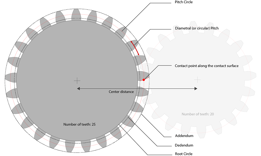
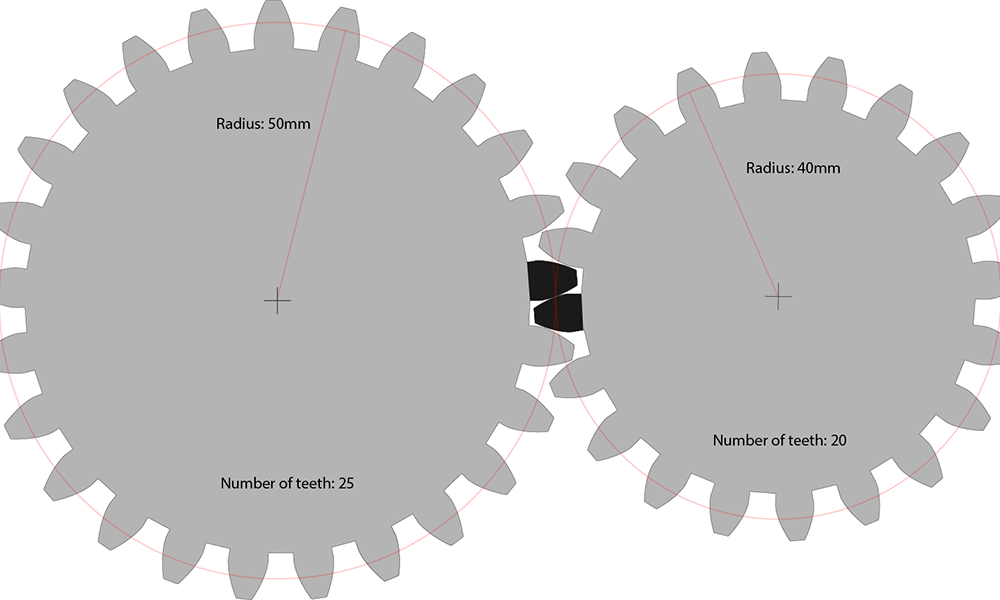
When designing a pair of gears, one also has to respect some size constraints related to how teeth will be touching each others. This characteristic is called the pitch circle and is located between addendum circle (end of the gear) and the root circle (the base of the gear).
The diameter of the pitch circle is determined by the number of teeth and a measure between two teeth (the pitch) or by the number of teeth and the module.
To help you understand this concept, take a look at this diagram:
Shape of the teeth
In order to keep an ideal motion transmission (i.e constant speed and torque), it is important to have a very specific shape. The most used are involute profiles that allow a continuous contact between two gears with a consistent contact angle and the least friction.
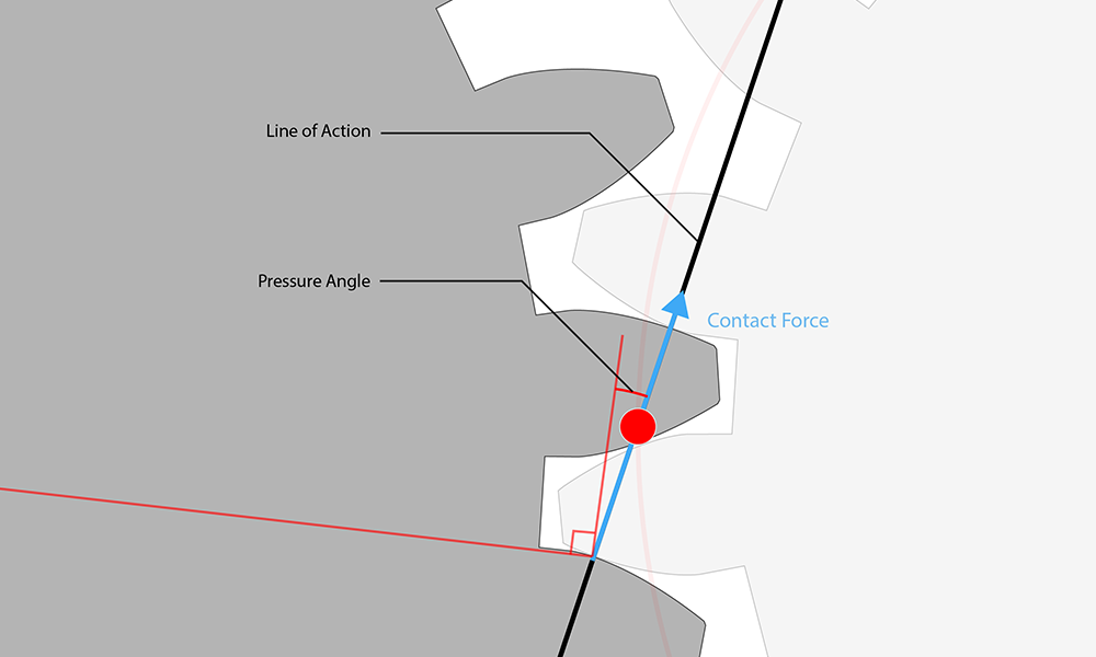
To determine the shape of the teeth, we use the pitch (or module) of the gear and the pressure angle.
The pressure angle is where the curve’s tangent and the gear axis are in contact.
With our POM material which does not need lubrication, you can use very low pressure angles to reduce friction. With standard profile teeth the pressure angle is set to 20° and it works well too on laser cut POM.
Do not forget about the Kerf!
Laser cutting is a subtractive technique that burns the material to cut and leaves a kerf. When burning the surface, the laser also leaves a kerf of a width that can vary, depending on the type of material and the thickness chosen. This has to be taken into account when designing for laser cutting.
If the gears you design do not require in-depth mechanical conditions (backlash, precision of the position…), the kerf can serve as a margin for the center-to-center distance.
Another aspect to take into account with laser cutting is the heat dissipation. When the laser hits the surface, the material is heated even aside where the laser the impact point, especially when the amount of details is high. The material cannot dissipate the heat fast enough and the material deteriorates. After the test we made on POM, these are the values you have to respect to reduce the effect:
| Thickness (mm) | 2 | 3 | 5 |
|---|---|---|---|
| Minimum distance between two paths (mm) | 2 | 3 | 5 |
Number of teeth
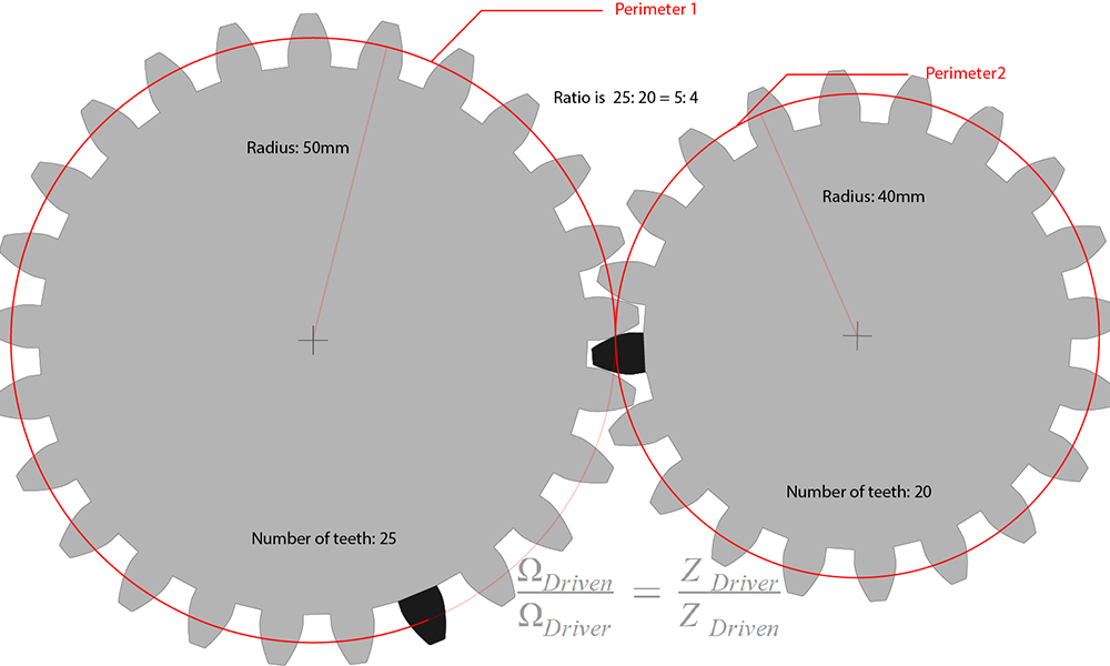
The number of teeth is the characteristic that determines the torque ratio of your gear.
When designing gears, we recommend you to respect a minimum number of teeth of 17. Under 17 teeth, the two gears cannot properly turn. They will interfere with each other and you will have to correct your design very precisely. However, if your design contains margins, this issue can be counterbalanced.
Tip: To avoid the same teeth to be always in contact, you have to use coincident prime numbers between the gears. The wear applied on the teeth will be homogenized.
Material used and surface aspect
Our best laser cutting material for gears is the POM (Polyoxymethylene, commercial name Delrin or Duracon). It is an engineering thermoplastic with very good mechanical properties: strong resilience, very good elongation at break, surface resistance to dirty environment and solvents.
Our POM is available in two colors: white and black. The available thicknesses are 2 mm, 3 mm and 5 mm. With the custom material option, you can ask for special material. To learn more about this feature, check this blogpost.
If you liked this article, please feel free to leave a comment and to share it on Facebook, Twitter and Linkedin


 Connect with Google
 Connect with Facebook