Simulation for Additive Manufacturing: Interview with Andreas Wuest from BASF S.E
Posted By Lucie Gaget on Oct 12, 2020 | 0 comments
Today, we present you an interview with Andreas Wuest, Head of Dynamic Structural Analysis, working at BASF S.E. and providing simulation services to BASF 3D Printing Solutions. Andreas Wuest is a mechanical engineer, working for BASF S.E in the field of Computer-Aided-Engineering (CAE) for many years. He is now heading a team that is taking care of dynamic structural analysis and took over the work to orchestrate 3D printing simulations and 3D printing activities concerning 3D printing solutions.
What is Simulation for Additive Manufacturing, for who is Simulation interesting and could it be an advantage for you to use these services? Let’s find out!
What is Simulation for Additive Manufacturing?
Simulation means you try to predict what is going to happen with the part in real life. You don’t need any part in your hands, it’s enough to have it virtually on the computer. Virtual engineering covers all things that are interesting to know, all-around 3D printing, from processing to using the part, from doing better designs to simulating tests.
The main method that is used is called the Finite Element Method (FEM), a numerical method, analyzing a model of reality in the computer. We are using the geometry we’ve built in a CAD system, this geometric model is translated in Finite Element Methods, it is broken up into many small parts, like small 3D puzzle pieces. The Finite Element Method basically consists of the knowledge of how these small particles behave when loaded by forces. When you know how one element reacts, you can easily use a computer to build those millions of 3D puzzle parts together, and then you can analyze how the whole part is working. This is the basis of Finite Element simulation.
How do you solve problems on parts for 3D printing?
Let’s say you have the bracket mounted to an engine, and some loads on the brackets to withstand. We first use the CAD geometry of the bracket as it is and mesh it with finite elements. Then we apply the loads which act on the part and start a nonlinear finite element calculation which analyses the stress and strain fields in the whole part. As we are using our own Ultrasim® based anisotropic material models we can clearly detect the zones where we reach the limits. Based on these results we can decide what to change to improve the situation. Sometimes we have to redesign the whole part, sometimes a contour change that homogenizes the surface stress is sufficient. These important insights are not available without a thorough numerical simulation.
We are not only focused on the part, we can also model the 3D printing process to some extent. This means we can induce material changes (e.g. anisotropy) and incorporate them in the mechanical simulation.
Another special thing at BASF is about material modeling. First thing, you need a computer model that is generated from CAD design, but you also have to know how the material is used in that part. How does this material behave when it’s loaded? It’s well-known that plastic materials they show some tricky behaviors sometimes, they are not easy to describe numerically, and one has to go through some special treatments to build those materials and what we can do is, we can use our methods and development we use for injection molding materials and transfer them into 3D printing materials. For example, if you take a part made with Powder Bed Fusion and that process has some strong anisotropies (they give you a directional dependency) then we are able to model this anisotropic behavior, it is possible to make precise simulations. We used this technology for basically every PBF part, e.g. an engine mount for Daimler.
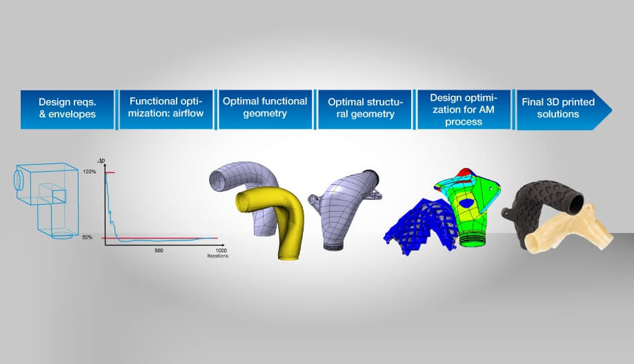
This process shows an example workflow how a design can be developed to an optimized functional part. In this case the optimal airflow was the target of our virtual engineering efforts and in the end you can see the final printed parts.
Why is it important to start thinking additive?
Quite often the designer doesn’t make use of the abilities and design freedom of 3D printing in the way he should. He sticks to some older design rules for injection modeling, he doesn’t understand how a 3D design can be, so we also help the designer to optimize the design by using optimization technologies such as topology optimization.
Thinking additive is essential. I also call it the “curse of experience”. We look at 3D printed parts, not injection molded ones. When people are looking for a part design, they build things based on their experience, based on what they know. They are not inventing something new.
Thinking additive is really getting rid of those constraints you used to have while using other manufacturing techniques. We would really like to support our customers in the ability to break rules and really do innovative new things, we need early contact. When the part has a problem but all the work has already been done and there is no possibility to change, then simulation can not contribute because simulation can only simulate that it doesn’t work and this is not the right use of simulation.
For what kind of projects is simulation relevant?
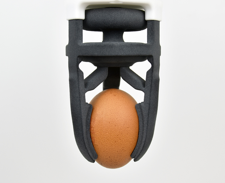
Everybody needs simulation, but not everyone knows that. Here is an example, we worked together with Alexandre d’Orsetti, Head of Sculpteo Studio, on a gripper. We had this inflatable structure with some connected gripping devices, all in one piece. There is an inflated part, moving and able to grip something. Of course, you can do something by design, with experience, but if you really want to dig into details and find out what you can maybe improve, what you can make lighter, reduce stresses, where you can predict if the gripper has enough pressure to hold a part. Asking for simulation earlier in the process is the key to get the full potential of simulation. Actually, the use of simulation is not well-known in the industry, by using it earlier, you can really predict issues, save time, and money.
3D printed gripper: One example where virtual engineering help to optimize the performance of 3D printed functional parts
How do you proceed while working with a customer, what are the different steps?
First, the customer approaches us with a specific problem. These problems can be really different: it can be a filament part that breaks too early, a powder bed fusion part that sometimes works, sometimes doesn’t work depending on how he puts it in the build space, another one can be a lattice structure in TPU that makes impact tests and sees the forces are too high, it has more damping, lower stiffness in order to prevent high loads for protection gear for example.
At first, we are listening and we try to understand what the problem is, and then, we look through our simulation glasses and try to find out how we could model the physics of that process that makes the problem and select our numerical methods. It can be standard force simulating to calculate stress and strain, it can be a dynamic calculation, a redesign of the part where you only look at a problem area and how that project evolves always depends on what the problem is – we have to understand first and then select our numerical weapons to solve the problem.
What kind of tools are you using?
We use all kinds of engineering software related to doing Finite Element Simulations. We have our Finite Element codes in-house, that we can use, and indeed many different finite element codes because some of them have their strengths and weaknesses, we can combine different tools.
Some customers work on one software, and another one with another software, we want to be compatible with them. Another thing to point out, we use a lot of optimization methods, mathematical optimization methods, that allow us to optimize the part for a special aspect, to minimize stress or maximize stiffness. These tools are used in-house like all kinds of topological optimization software, all kinds of parametric optimization, which is a more basic mathematical optimization. Last but not least we also have our own software this means that we sometimes do our own material models, interfaces, own code when we don’t find a solution coming out of other software!
We hope that this interview helped you to understand the role of simulation in the additive manufacturing process and that you see now all the potential of simulation for your next projects! Do you want to go further? Watch BASF live talks:


 Connect with Google
 Connect with Facebook

