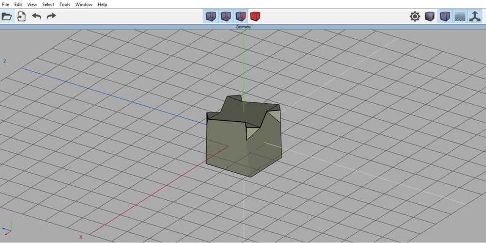
By opening the program, you land to the workspace of the Wings 3D software. The axis X,Y, Z are aligned in the same way as in most of the 3D design software. Each square is 1 unit per 1 unit. These units can be either meters, centimeters or millimeters, as there is no importance in scaling the model while designing. Scaling matters only when you export your 3D model to another 3D design software that uses a different scale system.
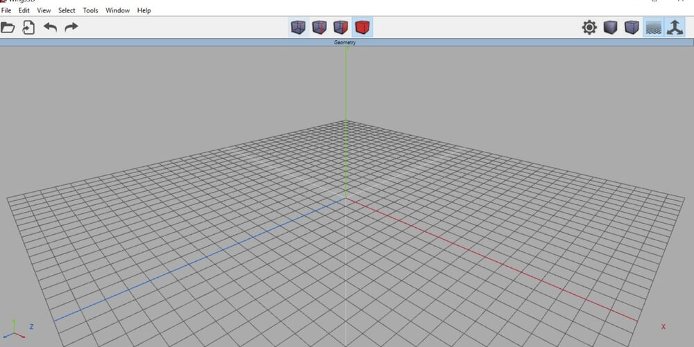
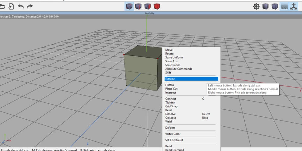
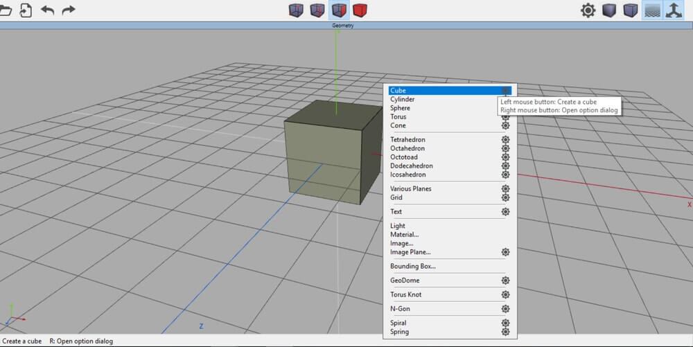
To get started, you can insert some basic shapes and experiment the different design tools. With an empty scene, right click on your mouse to get the whole context menu with the list of available options. There are many basic models, called primitives, and you can use them as a starting point for creating more complex 3D models. You can insert just one shape or multiple shapes you want to work with.
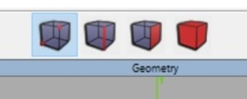
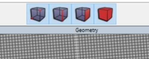
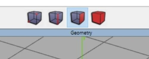
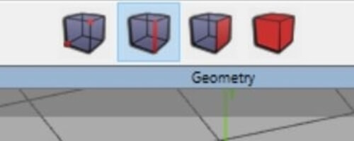
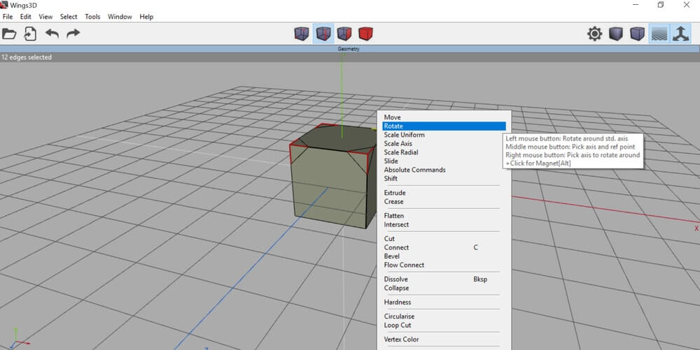
With these icons on the top of the screen, you can switch between selection modes: the vertex mode, the edge mode, the face mode and the object mode. You can use also the hotkeys instead (V=vertex, E=edge, F=face or B=body).
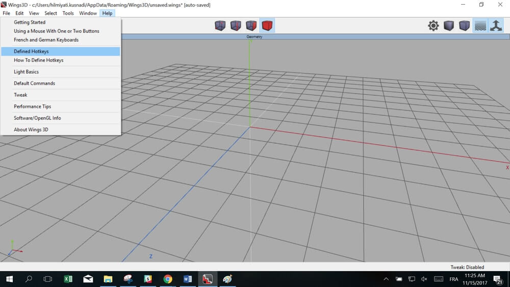
More information about how to define hotkeys can be found in the “Help Tab”.
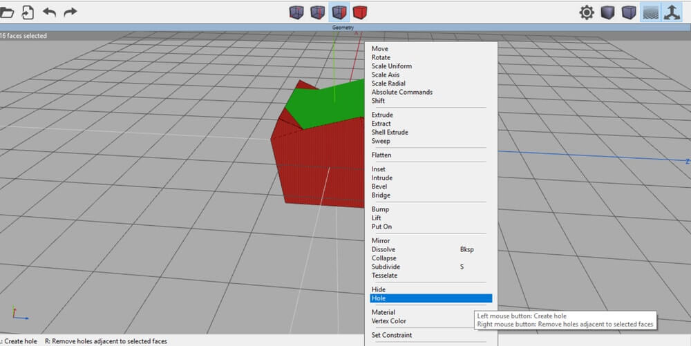
One of the best attributes of Wings 3D software is that you can switch between the different modes: Vertex mode, Edge mode and Surface mode. For example, you can start with edge mode, then change and use vertex mode, and then go back to edge mode again. Each time you want to modify, extrude, or hollow your 3D shape, you have to choose one of these modes. So, in order to create a complex design, you have to know which mode you should use each time and what possibilities each mode gives you.
So, let’s see one by one, these basic modes that are used in Wings 3D software.


 Connect with Google
 Connect with Facebook


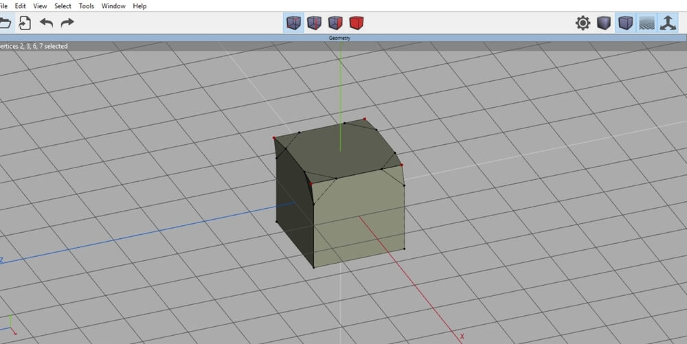
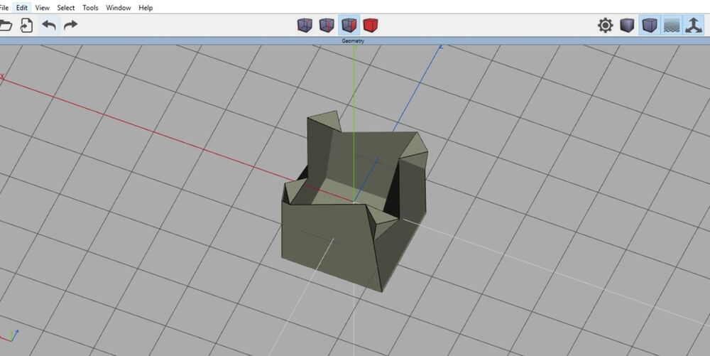
 Here’s the result for our 3D model: