 Connect with Google
 Connect with Facebook
Topology Optimization: Control the Shape of your 3D Printed Model
Posted By admin on Apr 26, 2017 | 0 comments
When designing for 3D printing, many components have to be taken into account in order to obtain a proper 3D printed object. Shape, stress, loads, mass are the main things to consider before starting to print. The topology optimization is one of the calculation methods that help you to obtain optimized CAD models before uploading it on our 3D printing service.
What is the Topology Optimization?
It is a technique that optimizes the geometry of an object thanks to a mathematical method, within a given space and with given loads and constraints. The goal is to maximize the performance of a part by reducing its mass.

The process of topology optimization
Designers and engineers use topology optimization to conceive parts but the parts optimized with this technique are often difficult to manufacture through traditional manufacturing methods.
Topology optimization is part of our Agile Metal Technology suite. Our team is currently developing the Smart Design Optimizer and Automatic Lattice Generator tools which will allow you to automatically modify and optimize your 3D models. You can discover the AMT suite and the coming tools on this webpage.
Topology Optimization with Additive Manufacturing
The field where topology optimization helps the most is surely additive manufacturing. With 3D printing, it is known that the less material is used to manufacture the part, the better it is.
Indeed, a part that uses less raw material to be produced means that it will be lighter and cheaper.
Topology optimization has the capacity to improve 3D models with constrained parameters to enhance the shape and reduce the amount of material used.
Additive manufacturing doesn’t encounter the same limits as traditional manufacturing methods and can go further with shape optimization thanks to the ability of 3D printing to print complex parts.
Improving the shape of a CAD model
There are many ways to improve the geometry of your 3D model. The simplest is to upload your file on Sculpteo and use the multiple online tools designed to optimize your model before 3D printing.
The solidity check analyzes the solidity of each part of your model whereas the hollowing tool allows you to reduce the amount of material used by automatically hollowing the inside part of your model.
To optimize the shape of a model, you can also use the dedicated tools of some software:
- Fusion 360
- Inspire
- Cura
And many other software. You can also run a python script that optimizes the topology.
To learn more about the software you can use to improve your CAD file for 3D printing, you can visit our tutorial page.
Shape Optimization for 3D Printing with Fusion360
Autodesk Fusion 360 has a very interesting shape optimization tool. Let’s take a look at it!
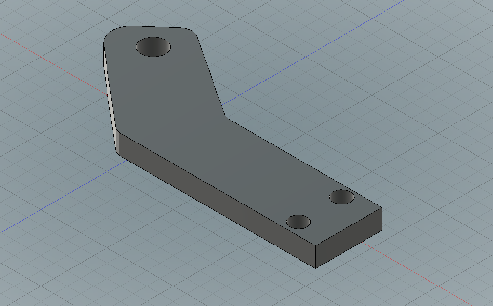
Our part is now ready to be optimized for 3D printing
For this example, we modeled a very simple bent arm with screws holes. Our model can be modeled in its actual shape but remember that the less material is used, the better it is.
In the workshop menu, select Simulation. A new window appears with all the types of simulation you can run.

Click on the Shape Optimization tool.

The software needs some parameters before starting the shape optimization process:
- Structural constraints: Set how your object will be constrained in the workspace. For our model, we set the constraints in the pins’ holes.
- Loads: choose where and how stress will be applied on the part. For our model, we applied a load of 500N (about 50Kg) on one side. This force will directly affect the shape of our model.
- Shape parameters: this section allows us to select the region of our model we want to preserve (holes and sides), if we want the model to be symmetrical and what amount of material we want to reduce. For our model, we set this last parameter to 50%.

Click on the picture to zoom in
Once the parameters are set, we can click on Solve.

The results of the study show how and where the stress is applied. The model can now be reworked to remove the excess material and to add supports where needed.

The results are displayed from dark blue (any stress) to red (lot of stress)

A small spot of stress appears in the middle of the part. Let’s see how we can use it
For our example, we output two different versions of the results:
- A version where we decided to not take the small stress point in the middle into account. The part is optimized but can have a weakness where we remove material.
- A version where we respected the results and added a support structure in the middle of the part. That extra support allows to handle most of the stress.

On this output, we decided to not take the small stress point into account

Here, we preferred to respect the stress spot and add some support structure in the middle of our part
Our part is now optimized and ready to be 3D printed with the best results.
To discover more about our 3D printing service, you can try it by uploading a file.
If you liked this article, please feel free to leave a comment and to share it on Facebook, Twitter and Linkedin