3D Learning Hub

MJF vs SLS: What's the Difference Between Multi Jet Fusion and Selective Laser Sintering?

Key Takeaways

  • Selective Laser Sintering (SLS) and HP Multi Jet Fusion (MJF) are industrial Powder Bed Fusion technologies used to manufacture strong, functional plastic parts without support structures.
  • SLS uses a high-power laser to fuse polymer powder, while MJF uses fusing agents and infrared energy, resulting in different production workflows and performance characteristics.
  • Both technologies offer excellent dimensional accuracy, mechanical properties, and design freedom, making them suitable for functional prototypes and end-use production parts.
  • SLS provides the broadest range of engineering materials, whereas MJF excels in productivity, repeatability, and medium-volume manufacturing.
  • The right technology depends on your project’s material requirements, production volume, mechanical performance, lead time, and budget.

Introduction

When selecting an industrial 3D printing technology, one of the most common questions engineers, designers, and manufacturers ask is: Should I choose Multi Jet Fusion (MJF) or Selective Laser Sintering (SLS)?

At first glance, these two additive manufacturing technologies appear remarkably similar. Both belong to the Powder Bed Fusion (PBF) family, both manufacture strong thermoplastic parts layer by layer, and both eliminate the need for support structures during printing. They are widely used for functional prototyping, tooling, low-volume production, and end-use parts across industries such as automotive, robotics, medical devices, consumer goods, aerospace, and industrial equipment.

However, despite these similarities, the two technologies rely on fundamentally different manufacturing processes. SLS uses a high-power laser to selectively fuse polymer powder, while HP Multi Jet Fusion uses inkjet printheads to deposit fusing agents before infrared lamps fuse the material. These different approaches influence production speed, dimensional consistency, material availability, surface finish, and the overall manufacturing workflow.

Choosing between SLS and MJF is therefore not simply a question of selecting the “better” technology. The best choice depends on your application’s requirements, including mechanical performance, production volume, material selection, cosmetic appearance, lead time, and budget.

MJF vs SLS

What is Powder Bed Fusion (PBF)?

Before comparing SLS and MJF, it is important to understand the manufacturing family they both belong to: Powder Bed Fusion (PBF).

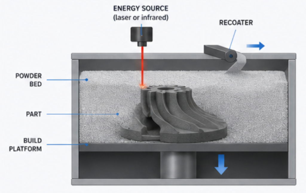
Powder Bed Fusion is one of the seven additive manufacturing process categories defined by the ISO/ASTM 52900 standard. It refers to manufacturing processes in which a thin layer of powder material is spread across a build platform and selectively fused using a controlled energy source. This operation is repeated layer after layer until a complete three-dimensional object is produced.

Unlike traditional subtractive manufacturing, where material is removed from a solid block through machining, Powder Bed Fusion builds components by adding material only where it is required. This layer-by-layer manufacturing approach significantly reduces material waste while allowing engineers to design highly complex geometries that would be impossible or prohibitively expensive using conventional manufacturing methods.

One of the defining characteristics of Powder Bed Fusion technologies is that the surrounding powder naturally supports the printed part throughout the build process. Because the unfused powder acts as a support medium, there is no need to generate additional support structures, unlike technologies such as Fused Deposition Modelling (FDM) or Stereolithography (SLA).

What is Selective Laser Sintering (SLS)?

Selective Laser Sintering (SLS) is one of the most mature and widely adopted industrial 3D printing technologies available today. Developed in the late 1980s, SLS has become a benchmark for manufacturing strong, accurate, and highly functional thermoplastic parts for both prototyping and production.

Unlike filament-based 3D printing technologies, SLS does not extrude molten plastic through a nozzle. Instead, it uses a high-power laser to selectively fuse microscopic polymer powder particles together, building the component one layer at a time directly from a digital CAD model.

The technology belongs to the Powder Bed Fusion family because each new layer begins with the deposition of a thin layer of powder across the build platform. Wherever the laser scans, the powder particles bond together to form a solid cross-section of the final part. The surrounding powder remains loose, supporting overhangs and complex geometries during the entire manufacturing process.

This unique manufacturing method enables engineers to design parts without worrying about support structures, unlocking a level of geometric freedom that is difficult to achieve using traditional manufacturing processes.

How does Selective Laser Sintering work?

Although the finished part may appear simple, the SLS manufacturing process involves a carefully controlled sequence of thermal and mechanical operations that ensure dimensional accuracy and excellent material performance.

SLS workflow

1. Preparing the digital model

The manufacturing process begins with a 3D CAD model created using computer-aided design software.

This model is exported as an STL or 3MF file before being imported into the build preparation software, where the part is oriented and sliced into hundreds, or even thousands of individual layers.

Each slice represents a cross-section that will be manufactured sequentially.

2. Preheating the powder bed

Before printing begins, the build chamber is heated to a temperature just below the melting point of the selected polymer.

This preheating stage plays a crucial role in the manufacturing process. By bringing the powder close to its melting temperature, the laser requires significantly less energy to fuse the particles. This reduces thermal gradients, improves layer adhesion, limits internal stresses, and helps minimise warping during production.

Maintaining a stable thermal environment is essential for producing dimensionally accurate parts with consistent mechanical properties.

3. Spreading a thin powder layer

Once the chamber reaches the required temperature, a recoater spreads a thin, uniform layer of fresh polymer powder across the build platform.

For most SLS materials, this layer measures between 100 and 120 microns, roughly the thickness of a human hair.

Uniform layer deposition is critical to ensuring consistent density, dimensional accuracy, and mechanical performance throughout the build.

4. Laser sintering

A high-power CO₂ laser then scans the powder bed according to the sliced geometry.

Only the areas corresponding to the digital model receive laser energy. The powder particles in these regions fuse together to create a solid layer, while the surrounding powder remains loose.

Because the laser only scans the required geometry, complex internal cavities, lattice structures, snap-fit mechanisms, and enclosed channels can all be manufactured without additional supports.

5. Building the part layer by layer

Once one layer has been completed, the build platform lowers by one layer thickness.

A fresh layer of powder is deposited across the surface, and the laser repeats the process.

This sequence continues hundreds or thousands of times until the complete component has been manufactured.

The finished part remains completely embedded inside the surrounding powder cake throughout the build.

6. Controlled cooling

After printing, the build cannot simply be removed from the machine.

The entire powder bed must cool gradually over several hours.

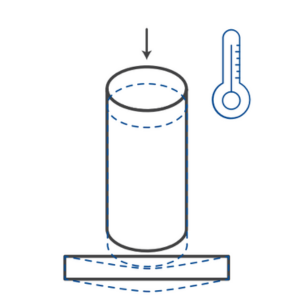
This controlled cooling phase is essential because polymers shrink as they cool. Cooling too rapidly would generate significant internal stresses that could cause deformation, cracking, or dimensional inaccuracies.

Although this stage increases the total production time, it plays a major role in the exceptional dimensional stability achieved by industrial SLS systems.

7. Depowdering and post-processing

Once cooled, the build unit is removed from the printer and the parts are carefully extracted from the loose surrounding powder.

The remaining powder is removed using compressed air, brushes, or specialised depowdering equipment.

Depending on the application, the parts can then undergo a range of post-processing operations, including:

These finishing processes improve aesthetics, surface quality, and functional performance while preparing the part for its final application.

What is Multi Jet Fusion (MJF)?

Multi Jet Fusion (MJF) is an advanced industrial 3D printing technology developed by HP to manufacture high-quality thermoplastic parts with excellent dimensional accuracy, consistent mechanical properties, and high production efficiency. Since its introduction in 2016, MJF has rapidly become one of the leading additive manufacturing technologies for functional prototyping, bridge manufacturing, and low- to medium-volume production.

Like Selective Laser Sintering (SLS), Multi Jet Fusion belongs to the Powder Bed Fusion (PBF) family of additive manufacturing technologies. Both processes manufacture parts layer by layer from polymer powder and eliminate the need for support structures thanks to the surrounding unfused powder.

The major difference lies in how each layer is fused.

Rather than using a laser to scan each cross-section individually, Multi Jet Fusion uses an array of high-precision inkjet printheads to deposit functional chemical agents onto the powder bed. The entire layer is then exposed to infrared energy, which selectively fuses only the areas where the fusing agent has been applied.

This approach allows MJF to fuse an entire layer in a single pass instead of tracing every contour with a laser. As a result, the technology offers excellent productivity while maintaining outstanding dimensional consistency across the entire build volume.

How does Multi Jet Fusion work?

Although MJF and SLS both manufacture parts from polymer powder, the printing workflow differs significantly. Instead of relying on a laser to selectively fuse the powder, Multi Jet Fusion combines inkjet technology, thermal management, and infrared energy to build each layer.

Let’s look at the complete manufacturing process.

MJF Workflow

1. Preparing the digital model

Like every industrial additive manufacturing process, Multi Jet Fusion begins with a three-dimensional CAD model.

The design is exported as an STL or 3MF file before being imported into HP’s build preparation software. During this stage, engineers determine the optimal orientation of the parts, arrange multiple components within the build volume, and generate the individual layers that will be manufactured.

Because MJF does not require support structures, many different parts can often be nested efficiently within the same build, maximising machine productivity.

2. Heating the build chamber

Before printing starts, the machine heats the powder bed close to the melting temperature of the selected material.

Maintaining a carefully controlled thermal environment is essential for ensuring uniform fusion throughout the build. By reducing the temperature difference between the deposited powder and the energy source, thermal stresses are minimised, improving dimensional stability and reducing the risk of warping.

This controlled heating also contributes to the excellent repeatability for which MJF is known.

3. Depositing a fresh powder layer

A recoater spreads a thin layer of fresh thermoplastic powder evenly across the build platform.

Multi Jet Fusion typically uses 80-micron layers, allowing the production of highly detailed features while maintaining short build times.

Uniform powder deposition is critical for achieving consistent density, excellent surface quality, and reliable mechanical properties.

4. Depositing the fusing and detailing agents

This is where Multi Jet Fusion differs fundamentally from Selective Laser Sintering.

Instead of scanning the powder with a laser, industrial inkjet printheads travel across the powder bed and selectively deposit two different chemical agents.

Fusing agent

The fusing agent is deposited wherever solid material should be created.

This dark liquid absorbs infrared energy much more efficiently than the surrounding powder. During the next step, these regions heat rapidly and fuse together, forming the next solid layer of the component.

Detailing agent

A second liquid, called the detailing agent, is deposited around the edges of the printed geometry.

Rather than promoting fusion, the detailing agent helps control heat diffusion by limiting the spread of thermal energy beyond the intended boundaries. This improves edge definition, sharp corners, small features, and overall dimensional accuracy.

The combination of these two agents allows HP Multi Jet Fusion to achieve exceptional detail while maintaining high production speeds.

5. Infrared fusion

Once both agents have been deposited, infrared lamps pass across the build area.

Only the regions coated with the fusing agent absorb sufficient infrared energy to melt and fuse the polymer particles together.

The surrounding powder remains loose and unfused, naturally supporting the component during printing.

Because infrared energy is applied across the entire build surface rather than following individual laser scan paths, each layer can be processed very efficiently.

This layer-wide fusion strategy is one of the key reasons why Multi Jet Fusion is recognised for its excellent productivity in industrial manufacturing.

6. Repeating the process layer by layer

After one layer has been completed, the build platform lowers by one layer thickness.

A fresh layer of powder is spread across the surface, the printheads deposit the functional agents, and the infrared lamps fuse the required geometry once again.

This sequence is repeated hundreds or even thousands of times until every component within the build has been manufactured.

Because the loose powder supports every feature throughout the process, engineers can design intricate internal channels, lightweight lattice structures, snap fits, and enclosed mechanisms without requiring support material.

7. Controlled cooling

Like SLS, Multi Jet Fusion parts cannot be removed immediately after printing.

The entire build unit must cool gradually inside a controlled environment before unpacking.

Slow cooling reduces thermal gradients throughout the part and helps preserve dimensional accuracy while minimising internal stresses that could otherwise cause distortion.

Although cooling contributes significantly to the total production time, it is essential for producing repeatable industrial-quality components.

8. Depowdering and post-processing

After cooling, the build unit is transferred to the unpacking station.

Operators carefully remove the loose surrounding powder using compressed air, vacuum systems, or dedicated depowdering equipment.

Unused powder is recovered, refreshed with virgin material according to validated refresh ratios, and reused in future production builds, helping to improve material efficiency and reduce waste.

Depending on the application, finished parts can then undergo a variety of post-processing operations, including:

These finishing operations enhance both the appearance and functional performance of the final component.


MJF vs SLS: What are the main differences?

Although Selective Laser Sintering and Multi Jet Fusion may produce visually similar parts, their manufacturing principles are fundamentally different.

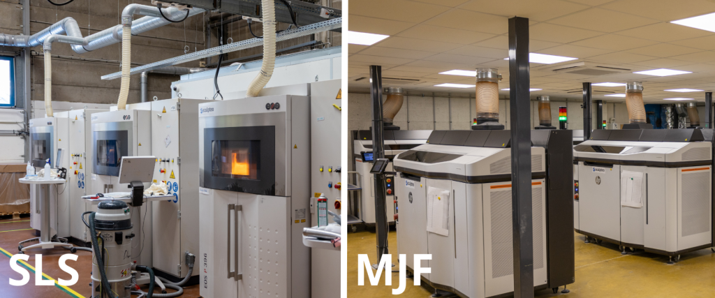
The most obvious distinction is the energy source. SLS relies on a high-power laser that selectively scans and sinters each layer of powder, while MJF uses industrial inkjet printheads to deposit functional agents before infrared lamps fuse the selected regions.

This difference influences several aspects of the manufacturing process.

In SLS, the laser must physically trace every contour and internal feature of the part. As part complexity increases, the laser scanning path becomes longer, which can affect build duration. In contrast, MJF processes each layer by applying agents across the build surface before exposing the entire layer to infrared energy, making the process highly productive regardless of geometric complexity.

The two technologies also differ in their material ecosystems. SLS has been commercially available for several decades and supports one of the broadest portfolios of polymer materials, including PA12, PA11, glass-filled nylons, carbon fibre-reinforced materials, ESD-safe polymers, aluminium-filled composites, and flexible TPUs. MJF, while offering a smaller material selection, provides a growing portfolio that includes PA12, PA11, polypropylene (PP), and TPU, all optimised for HP’s manufacturing platform.

Another difference lies in mechanical consistency. Thanks to its highly controlled thermal management and layer-wide fusion process, Multi Jet Fusion is often recognised for producing parts with very uniform mechanical properties throughout the build volume. SLS also delivers excellent performance but may exhibit slightly greater variation depending on part orientation, geometry, and thermal history.

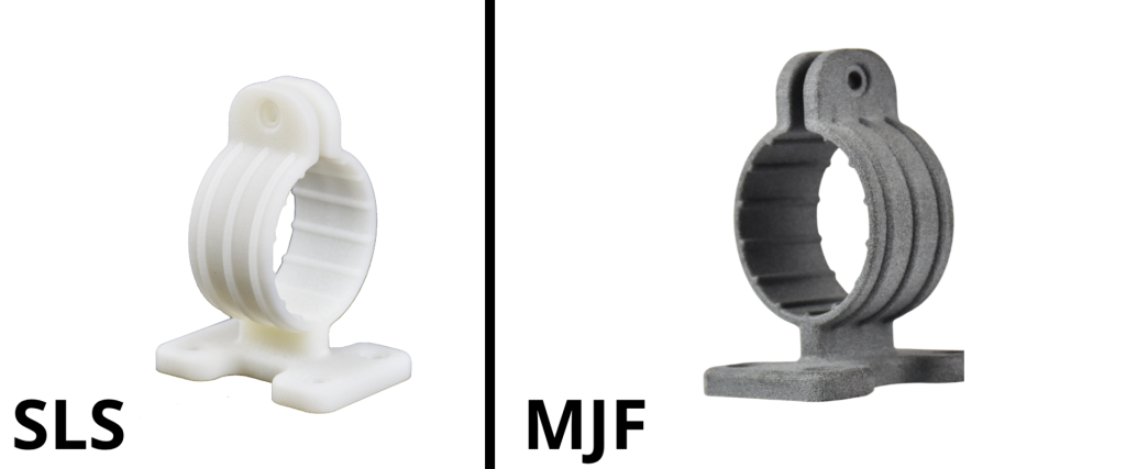
Finally, cosmetic appearance can vary slightly between the two processes. Raw SLS parts typically exhibit a slightly lighter, grainy finish, while MJF parts usually have a characteristic grey appearance due to the fusing agent used during manufacturing. Both technologies, however, can be enhanced through post-processing such as dyeing, polishing, painting, or chemical smoothing to achieve high-quality finished components.

SLS vs MJF

MJF vs SLS: Materials comparison

AVAILABLE AT YOUNG'S MODULUS TENSILE STRENGTH ELONGATION AT BREAK MELTING TEMPERATURE SHORE HARDNESS CHARPY IMPACT TEST (NOTCHED) CHARPY IMPACT TEST (UNNOTCHED) HDT B (0.45 MPa, DRY) CERTIFICATIONS
SLS Technology PA12 1700 ± 150 MPa 45 ± 3 MPa (X-Y) 11% - (Z) 3-9% min. 172°C, max. 180°C 75 ± 2 D 4,8 ± 0,3 kJ/m² - 154°C Food assessment REACH
PA12 Grey GF 3200 MPa 51 MPa 9% 185 - 188 °C 80 D - - - -
PA2210 FR 2500 (dry) MPa 2400 (cond) MPa 46 (dry) MPa 43 (cond) MPa 4% (dry) 7% (cond) 185°C - - - - Blue card UL-94V-0
Ultrasint® TPU 88A 75 MPa 8 MPa X: 270% Z: 130% 120 - 150 °C 88 - 90 A No break - - Biocompatibility certificate upon request
PA11 XY: 1750 MPa Z: 1800 MPa(dry) XY: 52 MPa Z: 54 MPa(dry) XY: 28% Z: 24%(dry, 23°C) 203°C - XY: 5.1 MPa Z: 3.9 MPa(dry) XY: 184 MPa Z: 85 MPa(dry) 176°C Food contact Biocompatibility
Ultrasint® PA11 ESD XY: 3150 MPa Z: 2150 MPa(dry) XY: 65 MPa Z: 55 MPa(dry) XY: 20% Z: 23%(dry, 23°C) 204°C - XY: 6.6 MPa Z: 4.7 MPa(dry) XY: 80 MPa Z: 90 MPa(dry) 186°C -
Ultrasint® PA11 CF XY: 5900 MPa Z: 2500 MPa(dry) XY: 82 MPa Z: 55 MPa(dry) XY: 7% Z: 11%(dry) 202°C - XY: 6.4 MPa Z: 4.7 MPa(dry) XY: 54 MPa Z: 33 MPa(dry) 189°C -
PA12 (blue) - XY / Z 46 / 40 MPa XY / Z 30 / 3,5 % 100°C for 15 minutes or 70°C for 2 hours - - - - Declaration of conformity available upon request
PA12 GF 4068 MPa 26 MPa 1,4 % 185 - 188 °C 77 D 41 J/m 123 J/m 179°C Safety Data Sheet (FR)
AVAILABLE AT YOUNG'S MODULUS TENSILE STRENGTH ELONGATION AT BREAK MELTING TEMPERATURE SHORE HARDNESS CHARPY IMPACT TEST (NOTCHED) CHARPY IMPACT TEST (UNNOTCHED) HDT B (0.45 MPa, DRY) CERTIFICATIONS
MJF Technology PA12 XY: 1700 MPa Z: 1900 MPa 50 MPa XY: 17% Z: 9% - - - - - Biocompatibility PAHs certificate RoHS/REACH UL94 and UL746A
PA12 S 1700 MPa 43-45 MPa 12% - - - - - -
Polypropylene 1600 MPa 29 MPa X/Y: 20% Z: 14% - - - - 100°C -
Ultrasint® TPU01 85 MPa XY: 9 MPa Z: 7 MPa XY: 280% Z: 150% 120-150°C 88 - 90 A No break - - Biocompatibility
PA11 XY: 1700 MPa Z: 1800 MPa 54 MPa XY: 40% Z: 25% - - - - - Biocompatibility
PA12 FR XY: 2580 MPa Z: 2540 MPa 46 MPa XY: 4.7% Z: 4% - 2.7–2.8 kJ/m² (Izod) - - 172°C Safety Data Sheet (FR)
PA12 GB XY: 2800 MPa Z: 2900 MPa 30 MPa XY: 6.5% Z: 5.5% 186°C 2.7 kJ/m² (Izod) - - 173°C Safety Data Sheet (FR)

Why choose Sculpteo for SLS and MJF 3D Printing?

Choosing the right 3D printing technology is only part of the equation. Selecting the right manufacturing partner is just as important to ensure your parts meet your expectations in terms of quality, repeatability, lead time, and technical support.

At Sculpteo, we combine industrial-grade equipment, engineering expertise, and a fully digital manufacturing workflow to help companies accelerate product development and scale production with confidence.

Whether you need a single prototype, a small production run, or thousands of end-use parts, our manufacturing platform allows you to move seamlessly from design to production.

FAQ

Is MJF more accurate than SLS?

Is SLS better than MJF for materials and colors?

Is MJF better than SLS for larger quantities of parts?

Get the latest 3D printing news delivered right to your inbox

Subscribe to our newsletter to hear about the latest 3D printing technologies, applications, materials, and software.